 Certified Transmission

When a 2004 Toyota Camry with a 2.4-liter engine and U241E automatic transmission arrived at my shop, it carried a frustrating history. The previous shop had already replaced the transmission twice, and the vehicle still acted up. It started in the wrong gear, engaged harshly, and stored a persistent DTC P0776 (Pressure Control Solenoid 'B' Performance / Stuck Off, SL2). No diagnostic work had been performed before or after either replacement. At that point, the previous shop ran out of ideas and sent it to me.
This case is a textbook example of why parts replacement is never a substitute for proper diagnosis. The transmission was never the problem, and two expensive units later, the real fault was still quietly waiting to be found.
My first step was to verify the customer concern and confirm the stored code, P0776, was active. With this code present, the transmission enters a failsafe mode: it locks into a single gear, does not shift, and engages harshly when coming to a stop or pulling away. Interestingly, after the vehicle sat overnight and fully cooled down, it would operate normally for a short period before eventually acting up again. That heat-related clue would prove significant.
I reviewed the code-setting criteria carefully. P0776 sets when the PCM commands a specific gear but the actual gear ratio (calculated by comparing input shaft speed, intermediate shaft speed, and output shaft speed) does not match what was commanded. When that mismatch is detected, the PCM illuminates the MIL and stores the code. The transmission control logic then defaults to failsafe operation to protect internal components.
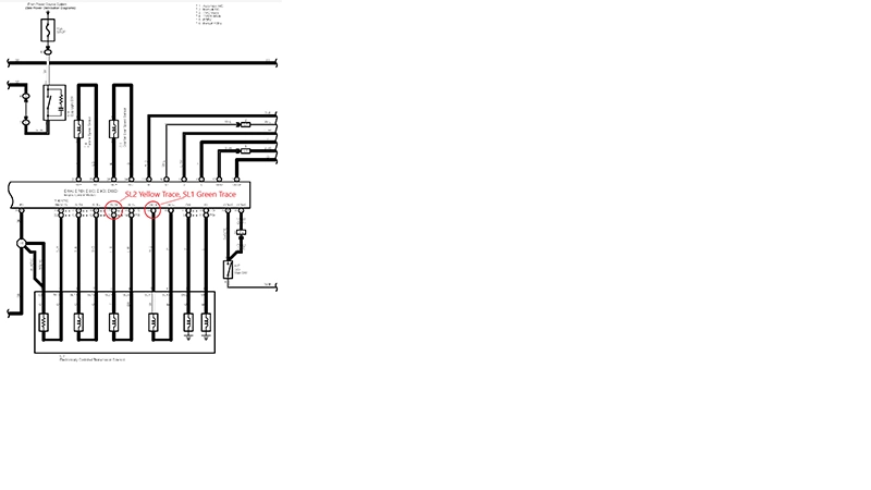
Before touching a test lead, I studied the wiring diagram to understand exactly how the U241E manages hydraulic pressure. This transmission uses a series of solenoids to regulate line pressure, throttle pressure, lockup clutch pressure, and accumulator pressure. The PCM provides both power and ground control for these solenoids; it does not simply switch one side of the circuit. Both the high and low sides are under PCM management, which makes this system well-suited to oscilloscope analysis.
I decided to scope the SL1 and SL2 solenoids directly at the PCM, which is conveniently located behind the glove box (easy access without pulling the dash). I probed SL1 at PCM pin 19 (green trace), SL2 at PCM pin 17 (yellow trace), and clamped an amp probe around the SL2 circuit wire (red trace) to monitor actual current flow. This three-channel setup would show me both voltage control and current delivery simultaneously.
Fig. 1 - Wiring diagram showing PCM solenoid control. SL2 monitored at pin 17 (yellow trace), SL1 at pin 19 (green trace), with amp clamp on the SL2 circuit (red trace).
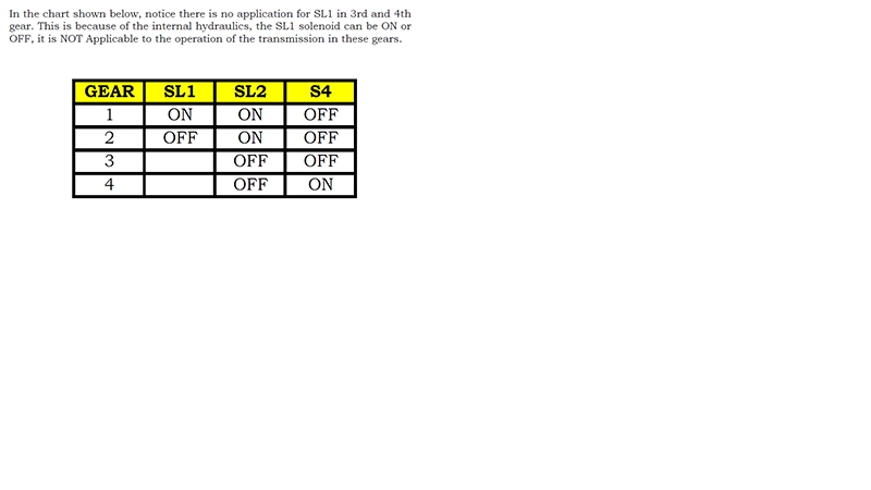
With the solenoid application chart in hand, I understood what to expect from each gear. In 1st gear, both SL1 and SL2 are commanded ON. When the transmission shifts to 2nd gear, SL1 turns OFF while SL2 stays ON. Both solenoids turn OFF for 3rd gear, and in 4th, the S4 solenoid comes into play. Importantly, SL1 has no applicable state in 3rd or 4th due to internal hydraulics, so it can be ON or OFF without affecting operation in those gears. This context is essential when reading the scope traces.
Fig. 2 - Solenoid application chart for the U241E. SL1 and SL2 are both ON in 1st gear; SL1 turns OFF in 2nd while SL2 remains ON. SL1 has no applicable state in 3rd or 4th gear.
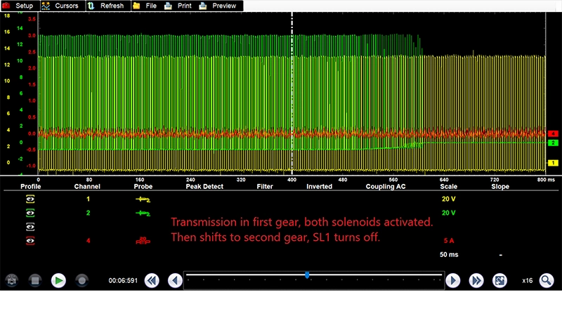
With the scope set up and the solenoid chart memorized, I headed out on a road test. For a significant period (several minutes of mixed city driving), and everything looked completely normal. The solenoids cycled correctly through the gears, SL1 and SL2 both activated cleanly in 1st, SL1 dropped out smoothly in 2nd, and the amp probe showed consistent current draw. The system appeared healthy.
Fig. 3 - Normal solenoid operation: transmission in 1st gear with both SL1 and SL2 active, then a clean 1-2 upshift with SL1 turning off.
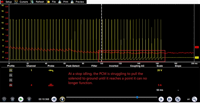
Eventually, while decelerating to a stop, the DTC set. I immediately saved the waveform. What I saw on the scope told the entire story.
Fig. 4 - The moment of failure approaching: SL2 (yellow trace) showing increasingly degraded ground pull-down as the PCM struggles to maintain control during deceleration to a stop.
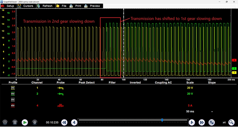
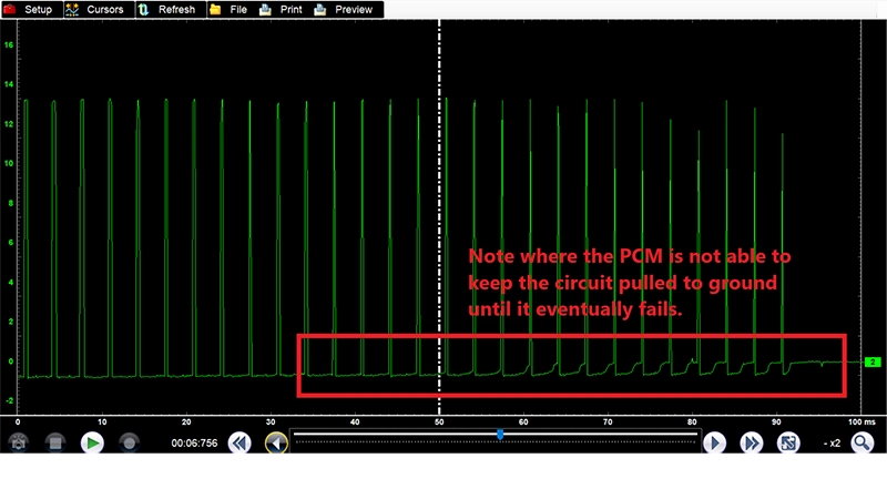
The scope data was conclusive. The PCM was losing its ability to hold the SL2 solenoid pulled to ground. As the vehicle came to a stop at idle, the SL2 control signal (which had been cycling correctly) began degrading. The voltage was not pulling down cleanly. The amp probe confirmed that current through the SL2 circuit was becoming erratic, then failing entirely. The PCM could no longer complete the ground path for SL2.
Fig. 5 - SL2 ground circuit failure captured on scope. The PCM can no longer hold the solenoid pulled to ground; the control signal collapses completely.
Once SL2 failed, the PCM responded exactly as designed: it shut off SL1 as well and placed the transmission into failsafe mode (3rd gear). With no valid solenoid commands, the transmission could no longer calculate correct gear ratios, which triggered the P0776 mismatch code.
Fig. 6 - After SL2 failure, the PCM shuts down SL1 as well, placing the transmission into 3rd-gear failsafe. Both solenoid signals go flat.
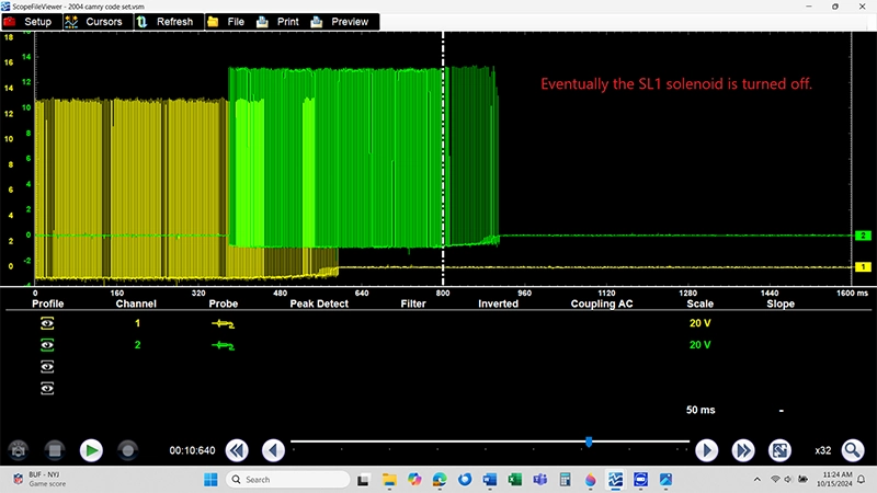
Fig. 7 - Zoomed view of the SL2 ground collapse. Note the waveform struggling to reach ground level before failing completely-a classic internal PCM output driver failure signature.
Ruling Out the Wiring - Ground Testing
Before condemning the PCM, I returned to the shop and performed comprehensive voltage drop testing on all PCM grounds. The PCM grounds on this application are located on the intake manifold and the engine block. I tested each ground circuit under load, looking for any resistance that might prevent the PCM from pulling the SL2 circuit to ground properly.
Fig. 8 - PCM ground locations on the 2AZ-FE engine (intake manifold and engine block). All grounds tested within specification-ruling out external wiring as the cause.

All grounds tested within specification. There was no voltage drop, no corrosion, no loose connections. The external wiring was not responsible for the failure. Combined with the scope evidence showing the PCM struggling to maintain the ground internally at the output driver stage, there was only one conclusion: the PCM itself was the fault.
The intermittent, heat-related nature of the failure also supported this diagnosis. Internal transistors and driver circuits in a PCM can function normally when cold and fail as they reach operating temperature; exactly the behavior this vehicle exhibited. A standard DVOM test on a cold vehicle would have shown everything in range. Only a scope, used during a real-world hot-condition road test, could catch the fault as it occurred.
This case is worth examining not just for what was found, but for how it was found. A DVOM would not have revealed this failure. A scan tool showing DTC P0776 provides a direction to investigate, not a repair. Even a comprehensive pressure test of the transmission would not have identified a PCM output driver as the root cause.
The oscilloscope, used during a real-world road test with the system under actual thermal load, captured exactly what was happening at the moment of failure. The waveform showed the SL2 signal losing ground control in real time. The amp clamp confirmed the current was failing at the same moment. There was no guesswork. There was no theory. There was data.
Without scope testing, the most logical next step after two failed transmission replacements might have been a third-or perhaps a wiring harness, or new solenoids-all of which would have again left the PCM in place and the problem unsolved.
After replacing the PCM with a known-good unit and performing a thorough road test under the same hot-soak conditions that triggered the original fault, the transmission operated flawlessly. Solenoid waveforms on the scope were clean and consistent through all gear changes. No codes returned. The harsh engagement was gone. The customer's Camry shifted properly for the first time in what had been a very expensive diagnostic journey at the previous shop.
The TakeawayThe takeaway is simple: diagnostic tools exist for a reason. A scope on the solenoid circuits for one extended road test accomplished what two transmission replacements could not. Invest in the test, not the parts.