A zero-mile failure that threw transmission codes before the vehicle ever left the bay looked like a bad unit-until a simple check revealed the transmission was fine and two connectors were not.
We've seen warranty claims on RE0F10D CVT units that showed no internal problem at teardown, which raised a hard question: were some of these failures really transmission failures at all? To find out, we bought a vehicle and began installing returned units into it for real-world testing. Several of those supposedly failed transmissions ran perfectly, and not just for a lap around the block; we put at least 2,000 miles on each one. Then one unit set the same codes listed on its warranty claim almost immediately. For a moment, it looked like we had finally found a truly bad transmission. We hadn't.
Not long after the RMA unit was installed at our Millard location, we got the call: the vehicle had set a P2765 while still in the shop and had not even been driven. Our first thought was the same one most techs would have: a failed sensor, a damaged reluctor wheel, or some internal issue we had not yet found. We had seen that code before and torn units down without finding anything wrong, so it was reasonable to assume we were headed down that road again. But zero-mile failures also come with one advantage: if the problem shows up before the vehicle leaves the bay, it almost certainly happened during installation or was already present in the vehicle.
Before we could even arrange to bring the vehicle in, Millard called back with the answer. The input speed sensor harness and the primary speed sensor harness had been swapped during installation. That was it. No bad sensor, no reluctor wheel damage, and no internal transmission failure.
What the Codes Were Telling UsThe original claim listed P0848, P0965, and P0746; codes that, at first glance, point toward a hydraulic or pressure-control problem. If you are working from that code list alone, it is easy to assume you are dealing with a bad unit. But once you know the speed sensor harnesses were reversed, the rest of the fault pattern starts to make sense.
The PCM expects a specific relationship between input and output shaft speed to confirm the ratio it commanded. When those signals are coming from the wrong location, that calculation falls apart. The module can no longer verify gear state correctly, and it begins logging faults that appear to implicate solenoids or hydraulic controls. In reality, those codes are downstream effects of bad speed information, not proof of an internal transmission problem.
The P2765 that was set immediately in the shop fits that pattern perfectly. It was an input speed sensor code, and the PCM saw zero input speed at idle in Park. That should never happen if the input speed sensor is connected correctly, because the input shaft is turning with the engine and torque converter in Park. If the input speed reading is zero, the signal is either missing or coming from the wrong place.
If the vehicle had been driven with the sensors swapped, the code list likely would have grown and looked even more like a serious transmission failure. That is what makes this issue so important: without checking the harnesses first, a technician could spend hours tearing down a perfectly good unit in search of a problem that is not inside the transmission at all.
Two Questions at IdleThe good news is that you can rule this out in under two minutes with a scan tool and the engine idling in Park; no road test, disassembly, or guesswork required.
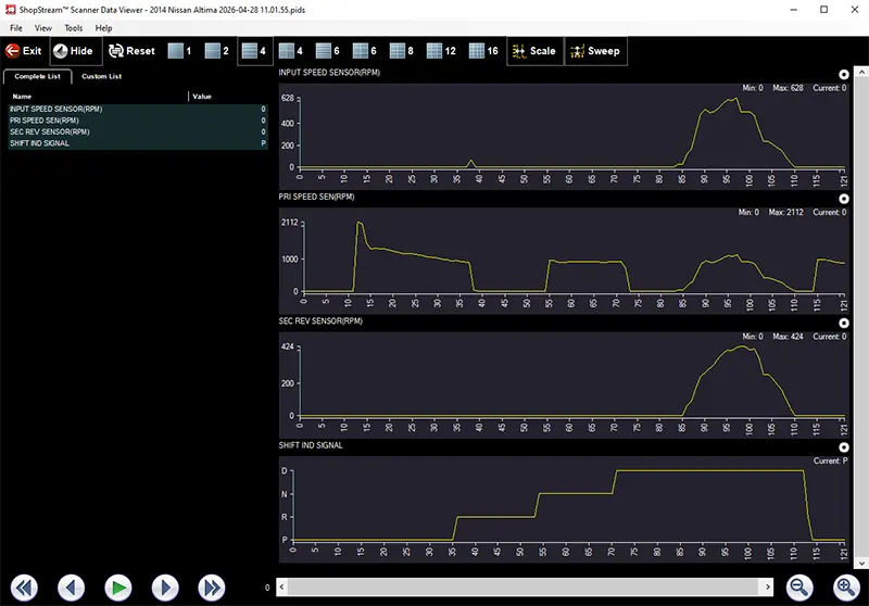
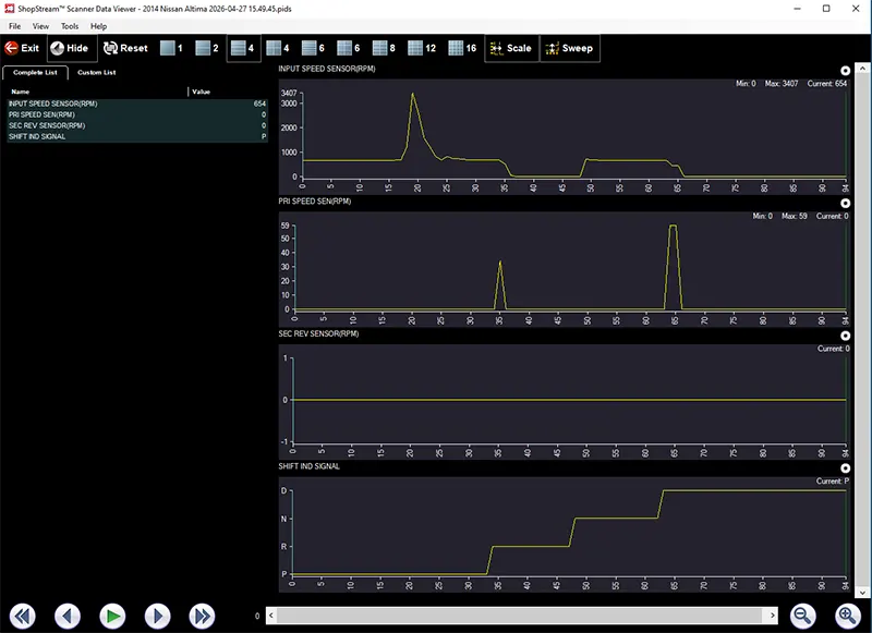
Start with two questions: What does the Input Speed Sensor read, and what does the Primary Speed Sensor read? In Park, the input shaft is turning with the engine and torque converter, so the ISS should be close to engine RPM, typically around 600 to 800 at idle. The output shaft is not moving, so the PSS should be at or near zero.
If those readings are reversed-ISS at zero and PSS near engine RPM-the harnesses are swapped. Correct them, clear the codes, and retest before the vehicle goes back to the customer. The logic is simple: with the engine running in Park, one shaft spins and the other does not. Correct sensor placement makes that obvious in the data; crossed connectors invert the picture.
When to Run This CheckThis is the kind of check worth making routine any time you see speed sensor or ratio-related faults on a fresh installation, especially when the code set does not quite match the condition of the unit in front of you.
- Any speed sensor DTC that sets on or immediately after installation
- Multiple ratio-related codes with no obvious hydraulic cause
- P0846, P0848, P0965, or P0746 on a fresh unit with no prior transmission history
- A fault code that sets in the shop at idle or in Park before the vehicle has been driven
- A zero-mile or very low-mileage failure where teardown finds nothing wrong internally
That point matters. If a returned unit tears down clean with no clutch damage, no valve body wear, no failed solenoid, that is not the end of the diagnostic story. It may be the clue that the problem was never inside the transmission in the first place.
A Word on Wire Colors and Sensor LocationWire colors on these speed sensor connectors can vary by year and application, so we are not publishing a universal color reference. Always verify the wiring diagram for the specific vehicle you are working on rather than relying on assumptions.
Sensor location is more reliable: the input speed sensor is at the front of the transmission behind the starter, and the primary speed sensor is at the rear in the end cover on the opposite side from the bellhousing. Knowing that before installation helps prevent the mix-up.
The Bottom LineWe are updating our own installation documentation to flag this issue, but the bigger lesson is broader than one unit or one code set. Simple verification steps still matter. A quick idle-in-Park scan tool check can confirm the installation, prevent unnecessary teardown, and keep a good transmission from being blamed for a problem it did not cause.
The bottom line is simple: speed sensor and ratio codes on a fresh installation do not automatically mean the transmission has failed. In this case, the unit was fine. Two connectors were on the wrong sensors. Check the simple things first - they may explain what appears to be a major transmission problem.