
A customer brought their 2014 Acura RDX to a neighboring shop with a transmission warning lamp illuminated. The shop performed a pre-scan of the vehicle systems and retrieved Diagnostic Trouble Code (DTC) P2720 - A/T Clutch Pressure Control (CPC) Solenoid Valve D Low Input. Aside from the warning light, the vehicle appeared to operate normally.
Believing the issue to be internal hydraulic pressure loss, the shop opted to replace the entire transmission. However, after installation, the same DTC reappeared-and now the transmission had no reverse gear. Further testing led the shop to conclude that the ECM was not providing voltage to the solenoid. They replaced and programmed a new ECM, but the problem persisted: same code, still no reverse. That's when I got the call.
Initial AssessmentWhen the vehicle arrived, I confirmed the presence of DTC P2720 and verified that reverse was inoperative. My next step was research. I needed to understand:
- How the system operates
- What conditions trigger the DTC
- The wiring diagram and connector pinouts
- Solenoid strategy, especially in relation to reverse gear
I came across an ATSG article describing a similar issue-P2720 and no reverse-caused by damage to the CPC Solenoid D connector following a minor accident. I performed a visual inspection of the connector and found no visible damage. Additionally, the installer should have noticed any connector issues during the R&R process, and none were reported.
Understanding Solenoid StrategyI located a solenoid strategy chart (Fig. 1) and confirmed that CPC Solenoid D should be ON in reverse, while Solenoids A, B, and C remain OFF. Since the DTC pointed to Solenoid D, and reverse was inoperative, I concluded that Solenoid D was not functioning as commanded.
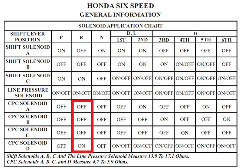
Figure 1
Next, I pulled the OEM wiring diagram (Figs. 2 and 4) and connector pinout (Fig. 3). The Honda/Acura 6-speed automatic transmission uses four CPC solenoids (A-D), each a 2-wire design. The PCM provides power to each solenoid, while the ground wires converge at splice C015, ultimately grounding at G101, located on the side of the intake manifold. The PCM controls the solenoids using pulse-width modulation (PWM).
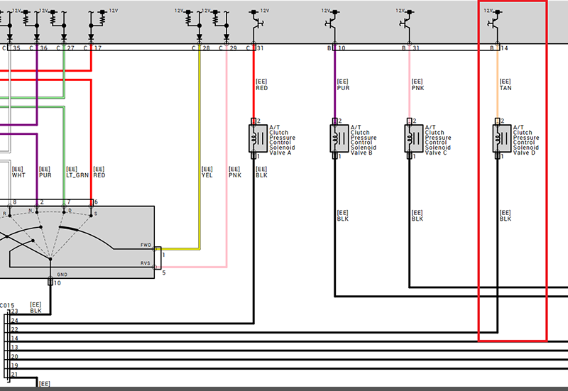
Figure 2
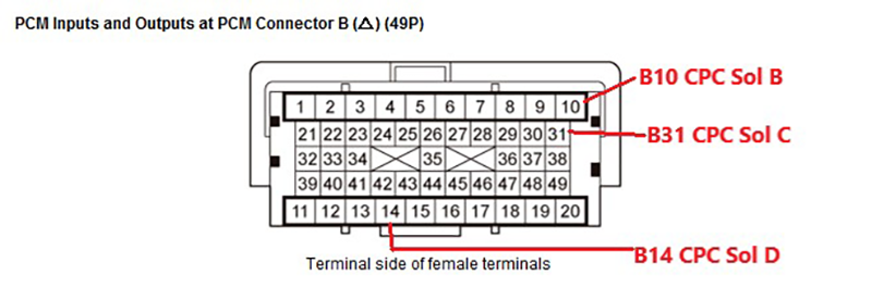
Figure 3
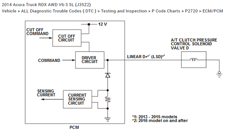
Figure 4
Understanding this strategy is critical. If Solenoid D is not energized during reverse, the hydraulic circuit cannot engage the reverse clutch pack. That's why a failure in this circuit-whether electrical or mechanical-can result in a complete loss of reverse gear.
Digging Into the CircuitThe original shop claimed the PCM wasn't supplying power to Solenoid D. That's where I started. I back-probed PCM connector B, pin 14 (tan wire), and also pierced the wire about 2 inches from the PCM and again at the solenoid. My goal was to verify continuity and voltage from the PCM to the solenoid.
Unfortunately, with a hard fault DTC set, the scan tool's functional solenoid test was disabled. I was hoping the system would perform a key-on self-test, and to my surprise-it did.
This vehicle uses a push-button start (smart key). With my scope leads connected, I turned the ignition on. I observed a brief voltage pattern on the scope, which quickly dropped to 0.0 volts.
My initial thought was that the PCM detected a fault and shut down power to Solenoid D.
Scope Analysis and ComparisonI captured the waveform and studied it. Something didn't add up. The voltage wasn't being pulled fully to ground-it dropped only to about 2.0 volts, not the expected near-zero. That suggested a ground-side issue, not a power-side fault.
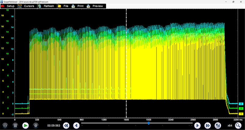
Figure 5
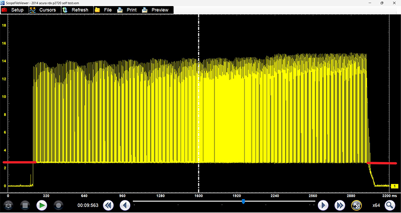
Figure 6
To confirm, I scoped a known-good solenoid-CPC Solenoid B. With the engine running, I observed a clean PWM signal cycling between 0.0 and 13.0 volts, with a noticeably shorter on-time than Solenoid D (Fig. 7). That comparison confirmed my suspicion: Solenoid D wasn't grounding properly.
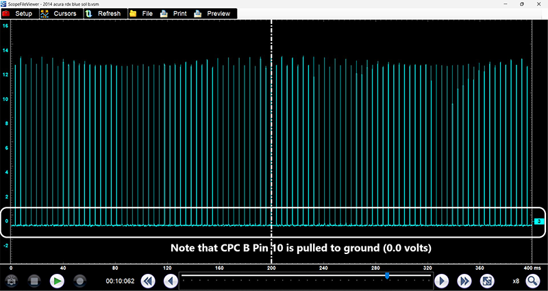
Figure 7
This is where experience and pattern recognition come into play. A technician unfamiliar with PWM signals might misinterpret the 2.0V low-side reading as a PCM fault. But in reality, it was a voltage drop caused by a poor ground connection-a classic case of electrical resistance in the return path.
The FixTo test my theory, I ran a jumper wire from the solenoid's ground wire directly to battery ground (Fig. 8). I started the vehicle. The DTC did not return, and reverse gear was now functional.
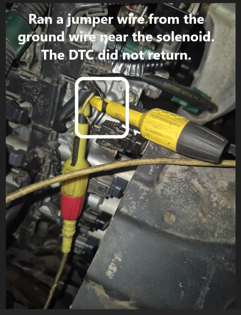
Figure 8
Clearly, the issue was a poor ground connection between the solenoid and the splice or ground point. I installed a new ground wire from the solenoid to a nearby chassis ground, reassembled the vehicle, cleared the DTCs, and performed a PCM/TCM relearn. I then road-tested the vehicle-the transmission operated flawlessly.
Lessons LearnedThis case is a textbook example of why testing is critical before replacing expensive components. The original shop replaced both the transmission and ECM, neither of which were faulty. The root cause was a simple ground fault-a problem that could have been identified with a scope and a wiring diagram.
Here are a few key takeaways for technicians:
- Understand the system before diving into repairs. Solenoid strategy and wiring diagrams are essential tools.
- Use a scope to analyze PWM signals. Voltage drop and waveform shape can reveal whether the issue is on the power or ground side.
- Don't rely solely on scan tools. When functional tests are disabled due to hard faults, look for self-tests or use manual triggering methods.
- Always verify grounds. A weak or corroded ground can mimic a failed solenoid or PCM.
- Test-don't guess. It saves time, money, and your reputation.
Final Thoughts
In today's diagnostic world, electrical issues are becoming more common-and more complex. As technicians, we must evolve beyond parts-swapping and embrace methodical testing. Whether it's a $2,000 transmission or a $1 ground wire, the principle remains the same: verify before you replace.