
We've all had those days where you roll into the shop ready to start the day and see a car waiting for you there in the parking lot and think, "Well, that look like trouble." When I came in to find a 2005 Mini Cooper waiting for me I felt my hopes for a peaceful morning wash away a just little bit.
The service adviser transcribed the customer's complaint as "Stuck in manual mode", and it was coming from a shop that didn't want to work on it. After chiseling the Midwest winter ice off the vehicle I was able to go through my initial check-out. I found code P0705 stored in the PCM (Transmission Position Sensor (P R N D L) Malfunction). Park, reverse, and neutral all functioned the way I expected them to, but the drive indicator did not illuminate when selected. However, the manual mode indicator did illuminate when drive was selected, but without moving the shifter over into manual mode. I also noted on the road test that the CVT would not change ratio in drive but would change ratio as designed when switched to manual mode, and shifted manually. Everything else on the car seemed to check out fine.
Normally, having a hard code set and duplicating the customer's concern right away ends in an easy evaluation, but that wasn't the case this time around. Just as I would for a relevant code on any check-out, I looked up the code description and set criteria but found nothing even remotely helpful. I checked a few forums and a couple of subscribed information sources for any leads. My fears were confirmed. I was finding that, like many European cars, there really wasn't much information out there for me. Identifix is usually a reliable source for decent wiring diagrams, and luckily, I happened to find one. (Figure 1)
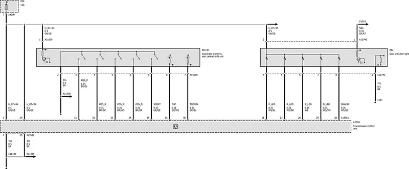
Figure 1
After looking over the diagram I was able to get a basic idea of how the system works, and as it turned out, was pretty simple. Armed with a little more knowledge, I prepared for my diagnostic routine. First, I wanted to ensure signal voltage was getting to pins 3,4,5,6, and 9. Second, I wanted to verify pin 2 was a good ground. Feeling confident I could figure this situation out, I asked the service adviser to sell some diagnostic time.
With my time authorized and wiring diagram in hand, I set out to get to the bottom of the situation. I pulled the center console out of the vehicle and located the shifter harness. I then looked for the brown/blue wire at pin 3 of the range sensor, labeled as "Park +". I was attempting to establish what the correct signals should look like, but guess what? None of the wire colors matched the diagram! This forced me to methodically work through the connector and write down what wires went where, and how the signals changed with range selection. I expected to see voltage on each wire when its corresponding range is not selected, then have the signal drop to 0v once selected. I had verified that pin 2 was a good ground by conducting a voltage drop test. I did find a couple things about the sensor's normal operation that I wasn't expecting.
First of all, the range sensor looks different than the conventional design I was used to. The shifter stick has a magnet on a spring which slides across the sensor. When shifting to manual mode the shifter is pushed to the right, and the magnet comes out of contact with the sensor. (Figure 2) shows what should be drive. (Figure 3) shows manual mode with the magnet relieved from the surface. If you have taken a close look at a 6R80 range sensor, it uses a magnet in a similar way minus pulling away to activate manual mode.
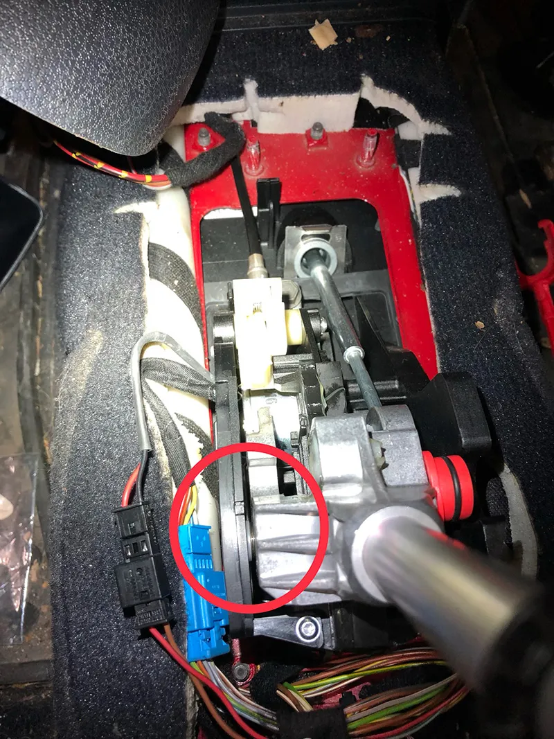
Figure 2
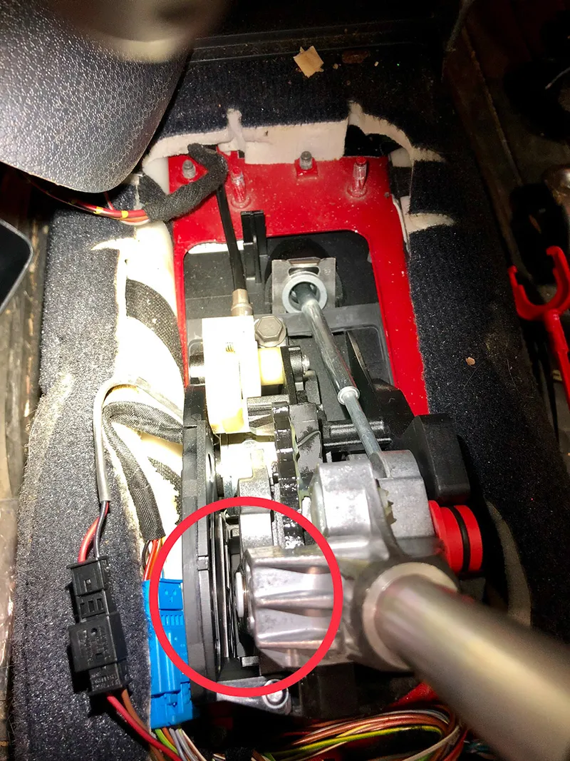
Figure 3
The second thing I was not expecting was the sensor voltages were very low by design. Open signal was only few tenths of a volt, right around 400mV. Voltage would drop to ground when the corresponding range position was selected, just as I expected.
Now that I had established a pattern of how the signals operated, I was able to pinpoint the cause. The anomaly I found was the manual mode signal wire never had any voltage no matter where the selector was. I put a little extra force on the shifter handle toward the sensor, and when the magnet was closer to the sensor, the signal for manual mode would come in and out intermittently. Simultaneously, scan data would indicate manual mode off (Figure 4). It seemed that the shifter bushings had just a tiny bit too much play in them, or perhaps the sensor's sensitivity to the magnet wasn't what it should be. With the sensor and the shifter being serviced and sold only as a complete assembly, I had our diagnosis in hand.
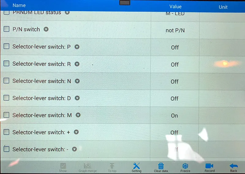
Figure 4
We contacted our local Mini dealer and procured a new O.E.M. shifter assembly. Should be easy from here on out, right? Nope, it's a Mini. Things got a little weirder since the shifter assembly installs from the underside of the vehicle. Sigh. With the new shifter in place I conducted a quick version of my previous testing to verify the repair. The same change in signals was present through the drive ranges and the manual modes operated and canceled the way they were supposed to.
We delivered the repaired vehicle back to the owner and received some praise for fixing something another shop was unwilling to tackle. Not much information was available, but in the end not much was really required. Stepping out into a situation with little service information can present some major challenges when trying to diagnose a problem. Stopping and taking a moment to analyze what you're really working with may show that it's not so complicated after all. Sometimes we just have to figure it out.