A 2005 Ford F-350 Super Duty equipped with a 5.4-liter engine and a 5R100W transmission presented with transmission-related diagnostic trouble codes. Situations like this are common in the field, and the way a technician approaches the problem can make the difference between a quick diagnosis and hours of unnecessary testing.
Whenever I approach an electrical diagnostic situation, my goal is to identify the most efficient path to locating the root cause of the issue. That process always begins with understanding the diagnostic trouble codes (DTCs), the system's theory of operation, and the code-setting criteria. Before reaching for tools or disconnecting components, it is critical to understand what the vehicle is trying to tell us.
In this case, the vehicle had the following codes stored:
- P0657 - Actuator Supply Voltage "A" Circuit/Open
- P0962 - Electronic Pressure Control (EPC) Solenoid Circuit Malfunction
Because these codes were not immediately familiar, the first step was to review the theory of operation and diagnostic criteria associated with them.
Understanding the CodesP0657 - Actuator Supply Voltage "A" Circuit/Open
Possible causes for this code include:
- Damage to the PCM connector (inspect for bent pins, corrosion, or moisture intrusion)
- An open circuit in the 12-volt actuator supply "A" circuit
- A failed PCM
The code sets under the following conditions:
- Engine running
- The PCM detects an open circuit condition on the actuator supply "A" circuit for one second
Based on this information alone, we can begin forming an initial hypothesis. Either the PCM has failed, or the actuator supply circuit is open, preventing voltage from reaching the transmission solenoids. However, forming a suspicion is not enough. It must be verified through proper testing.
P0962 - Electronic Pressure Control (EPC) Solenoid Circuit Malfunction
The second code, P0962, indicates that the PCM detected a low voltage condition on the Electronic Pressure Control (EPC) solenoid circuit. The EPC solenoid is responsible for regulating line pressure within the transmission. If the PCM detects voltage lower than expected in this circuit, it will set this diagnostic code. At first glance, this might appear to be a faulty EPC solenoid, but electrical diagnostic experience tells us that low voltage codes are often the result of a supply problem rather than a component failure. That leads to an important question: How does the PCM determine that the EPC solenoid does not have sufficient voltage?
How the PCM Monitors Solenoid CircuitsOn many American vehicles, transmission solenoids receive battery voltage from a relay, fuse, or power supply circuit, while the control module completes the circuit by providing the ground. When the solenoid is not grounded, battery voltage is present throughout the entire circuit. The control module monitors this voltage internally through its own voltage-sensing circuitry. This allows the module to perform a self-check of the circuit and detect faults such as opens or shorts.
While this monitoring strategy is common across many manufacturers, some companies-such as Mopar (Stellantis)-use slightly different strategies to monitor circuit integrity.
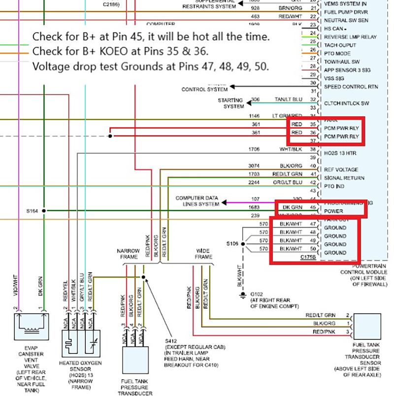
In this particular case, inspection of the PCM connector revealed no B+ voltage present at any of the solenoid pins. The affected pins were 1, 2, 10, 11, 12, 13, and 23 at the PCM connector. (Figure 1)
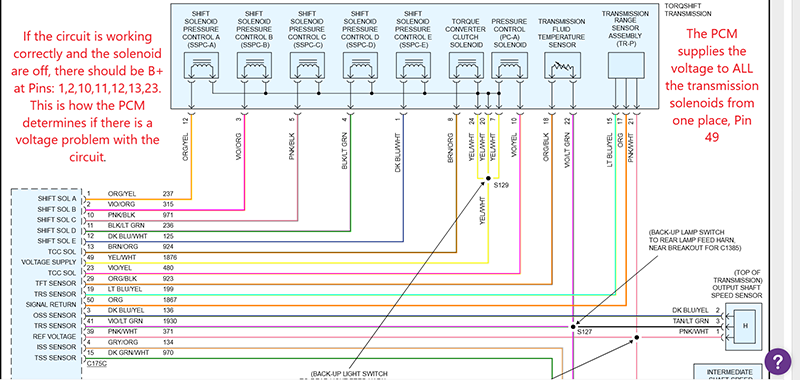
Because the PCM could not detect voltage on these circuits, it immediately set both P0962 and P0657.
Why Only One Solenoid Code?A logical question arises when encountering a situation like this: Why did the PCM only set one solenoid code instead of several? Many General Motors transmission control strategies, for example, will set a long list of solenoid circuit codes if transmission power is lost. In this case, the PCM appears to perform a sequential self-test of the solenoids. When the first solenoid in the test sequence fails due to the lack of voltage, the PCM shuts down the actuator supply circuit (either through a relay or an internal PCM switch) and sets the code. Once this happens, the PCM stops testing the remaining solenoids, which is why we do not see additional circuit codes.
However, the presence of P0657 provides an important diagnostic clue. This code indicates that the PCM cannot detect voltage in the actuator supply circuit, specifically at pin 49 of the PCM connector. This strongly suggests that none of the solenoids are receiving power, not just the EPC solenoid.
Beginning the Testing ProcessAt this point, we have spent approximately 10-15 minutes gathering information and analyzing system operation. Now it is time to move to the vehicle and begin testing our theory. The first step in any electrical diagnostic process should be an Electrical System Analysis (ESA). Before testing individual circuits, always verify the battery and charging system are functioning properly. Low system voltage can create misleading diagnostic results.
This includes checking:
- Battery condition
- Alternator output
- Starter current draw
- Battery terminal cleanliness and tightness
In this case, the vehicle passed the battery, charging, and starting system tests, allowing us to proceed with circuit diagnosis.
Testing the Actuator Supply CircuitHaving already performed basic checks, the PCM power and ground circuits were tested and confirmed to be operating correctly, including performing voltage drop tests on the ground circuits. With the PCM confirmed to have proper power and ground, attention turned to the actuator supply voltage circuit. We located connector C175C and identified the yellow/white wire at pin 49, which is responsible for supplying voltage to the transmission solenoids.
To test this circuit, I connected my oscilloscope directly to the wire. A digital volt-ohm meter (DVOM) could also be used for this test. When testing wiring, I typically pierce the insulation of the wire to ensure a solid electrical connection. Back-probing is another acceptable method, but it does not always guarantee a reliable connection if the probe does not fully contact the terminal.
With the test lead connected, I turned the ignition Key On Engine Off (KOEO) and observed the voltage reading. Based on the information gathered during code research, I expected to see 0 volts coming from the PCM, and that is exactly what the test revealed. To confirm the result, I cleared the codes and repeated the test. Once again, there was no B+ voltage present on the actuator supply circuit. At this point, we have confirmed that the PCM is not providing voltage to the actuator supply circuit, identifying the source of the problem.
Optional Verification of Solenoids and WiringIf additional confirmation is desired, it is possible to verify the wiring and solenoid integrity before replacing the PCM. To perform this test:
- Disconnect connector C175C at the PCM.
- Apply a fused B+ jumper wire to pin 49.
- Individually ground each solenoid control wire.
By placing an amp clamp on the power wire, you can observe the current draw of each solenoid and verify that the amperage falls within the manufacturer's specifications.
This test confirms that the solenoids and wiring harness are functioning properly, further supporting the conclusion that the PCM is the source of the failure. (Figure 2)