
A customer brought their 2013 Ram 1500 equipped with a 5.7L/65RFE powertrain to our shop with a complaint of, "Will not shift at times." A quick scan of the truck revealed a P0750 (Low/Reverse Solenoid Circuit) code. I took the vehicle for a road test and was able to duplicate the no shift issue after driving it a few miles. It was almost as if it needed to warm up a little before the code would reset and causing the transmission to go into fail safe mode.
After a quick visual inspection, I found that the fluid was full, red, and in average condition. The transmission also had no leaks. Having run into this code before and knowing that there are several different areas that could be an issue, I have seen the RFE series with a bad solenoid pack, a bad TIPM, bad connection, bad wires, and bad PCM. There is NO silver bullet for this code in a FCA vehicle, or maybe known as Stellantis now?
At this point it was time to get approval for additional diagnosis time from the customer. The customer granted the extra time, so I decided to first check the resistance across the low/reverse solenoid in question, finding 1.9 Ω which is normal for this application. (Figure 1)
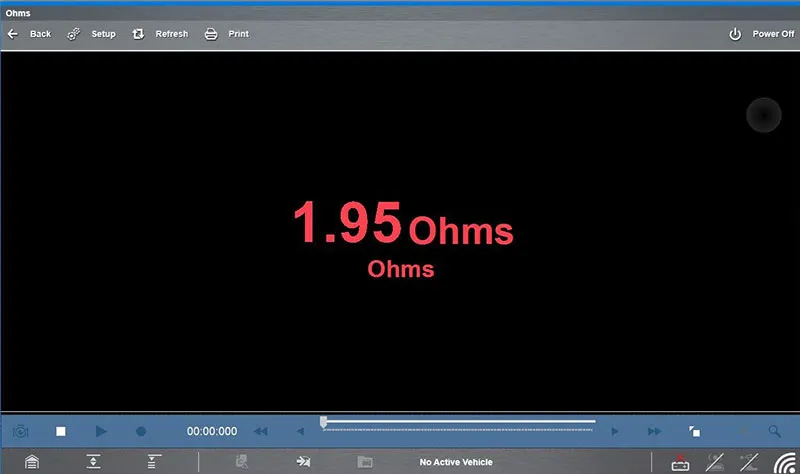
Figure 1
So off to work I went making sure the PCM was able to command the solenoid off and on consistently. I also needed to make sure that the solenoid control wire was not open or having high resistance, and that it was able to carry a load. I like to test this by using the control wire to light up a headlamp bulb; if the bulb stays on nice and bright I it should be good enough for a shift solenoid as well. After verifying the operating capability of the PCM and wiring I needed to turn my attention to the solenoid once again.
Remembering that the truck would only stop shifting after being driven a few miles, I could only assume that it the transmission needed to be warm before it would act up. This meant I would have to dive deeper into the solenoid?s ability to consistently operate throughout its full cold to hot temperature span.
This is where some training has paid off. Shortly after I became a diagnostician for Certified Transmission, my employer sent me to Dallas, TX for a week of training at Veejer Enterprises with Vince Fischelli. Vince founded Veejer Enterprises in 1985. He is a Technical Training Consultant specializing in vehicle electrical and electronics troubleshooting training for all segments of the vehicle service industry.
One of the many troubleshooting tips Vince showed us was to simply back probe the solenoid control wire and the power wire going into the transmission case connector. You can then observe the voltage with a lab scope or a voltmeter and see what that solenoid is doing while it is being energized. For this task I chose the lab scope in our Snap-On Zeus scanner simply because the response time is immediate, and the reading is more accurate. Typically, what you want to see is that the energized solenoid is using most, but not all, of the battery voltage being supplied to it if the electrical system has good integrity. When the load is present (in this case, the solenoid), whether you are working with a duty-cycled solenoid like what we have here, or an on/off solenoid, you want to see from 100mv to 800mv on the control side. I'm not going to say that 1V is always going to cause an issue, but it is getting close. If you are working with a good battery, what you want to see is about 11.5v to 12.5v being absorbed by that solenoid with roughly .5v of energy being unused at the other wire. At first, this is exactly what I had while diagnosing this truck.
However, the longer I monitored this voltage, the more inconsistent it became. After a couple of minutes, the lab scope began to get a very irregular pattern until it completely dropped out and went to 0v, so I turned the solenoid off with the scan tool and I caught this. (Figure 2)
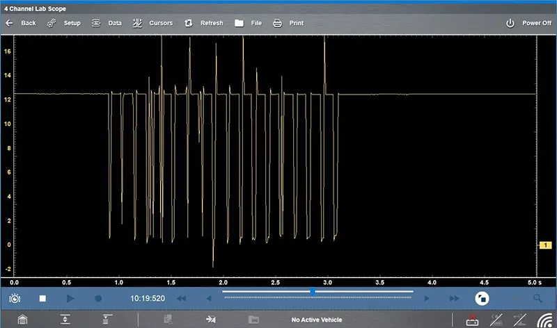
Figure 2
Now we were getting somewhere! A quick resistance check of that solenoid now revealed a reading of .17 Ω. (Figure 3)
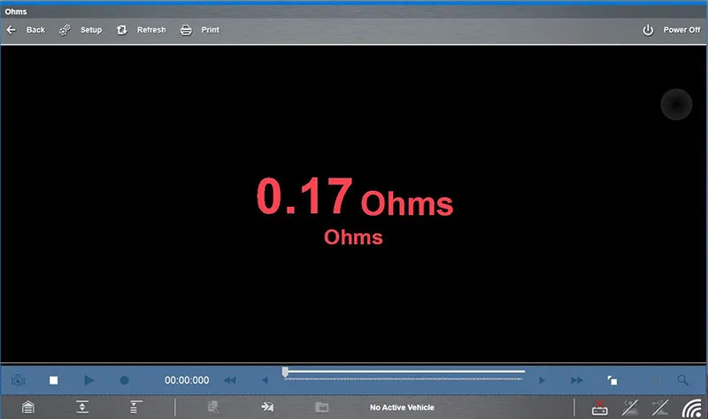
Figure 3
This may as well be considered a shorted solenoid at this point. It can safely be assumed that the longer this solenoid was being energized, the warmer it became. This type of action mirrored or duplicated a road test if you will, causing the solenoid to short out as it warmed up.
A clean pan and filter inspection revealed no debris indicating no other internal part failures. Now having a complete diagnosis of an intermittent faulty solenoid, we can be confident that a replacement solenoid pack will resolve the customer's complaint.
After the customer authorized the replacement of their solenoid pack, this repair along with a new filter installation was performed. Now it was time to verify that the issue was resolved. All codes in the truck were cleared and the vehicle was taken for a long test drive to be sure the complaint was resolved. There were no reoccurring codes, the truck performed flawlessly, and we had another happy customer with minimal expense incurred.
I cannot stress enough the importance of the good quality training I received from Veejer Enterprises. I am amazed at how beneficial this training has been for me and other countless technicians. The troubleshooting tips I learned and picked up at this class has made my job easier in so many ways. I would recommend it to any technician trying to better themselves with the additional knowledge gained in the world of automotive repair. It has saved me so much time in diagnosing different problems, and we all know time is money.