
A customer had brought in her 2010 Ford Escape equipped with a 3.0L Engine and the 6F35 transaxle. The customers concern with the vehicle was that the transmission slips intermittently. We started our evaluation with a quick visual inspection of the vehicle and checking fluids, all which check out good. Then I scanned the car with the scan tool; all of our locations have Snap-On Zeus workstations and I had two codes: a P0297, "Vehicle Over Speed Condition", and a P1500, "Vehicle Speed Sensor". No codes in any other modules. The next step was to go for a test drive and see if I could duplicate the complaint.
When cold, the vehicle worked correctly for about 10 minutes of driving, then out of nowhere the transmission acted like it had a mind of its own by shifting erratically. I also observed the speedometer going up and down while maintaining steady speed. I pulled up the output speed sensor PID on the scan tool and found it also was reading all over the place. (Figure 1) is from a startup without moving at all. I brought the vehicle back to the shop to do a visual inspection, and when I opened the hood I found the battery terminals were severely corroded, the fluid was slightly varnished and reddish brown in color, but had no burnt odor. I have had several speed signal issues before that I had resolved with cleaning the battery terminals and the grounds connected to it, so I figured it needs to be done anyway and could possibly take care of the issue.
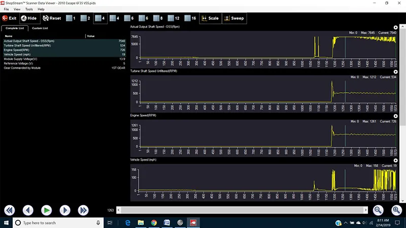
Figure 1
I cleaned the battery terminals and performed the battery and charging system test. It had passed and did not even pick up any AC ripple, which kind of surprised me because I expected to see erratic test results here. I went for another test drive and it was still acting the same way. Upon returning to the shop again I brought up service information on the PC and checked to see if any TSB's were available for either of these DTCs, and none were found relating to this particular issue. I also looked at a few other resources I have access to and again found nothing.
The next step was to get into some in-depth electrical testing. I printed off the appropriate wiring diagram so I could see how the circuit works and what to expect. I also printed off the diagnostic flowchart; the flowchart for the P0297 did not reveal much information and the one for the P1500 was going in different directions depending on the application. To make matters worse, the information was confusing due to the pin numbers not matching the connectors on my application. After I got that all straightened out and I knew what I was looking at, I continued on with my testing.
I checked to see if I had good battery voltage for the sensor at the case connector and it checked out fine. Next I wanted to make sure the ground circuit was good since the battery had a lot of corrosion. I only had 0.05v voltage drop on that circuit which is a good ground, so I knew that was not the cause, either. I decided it was time to get the scope out and take a look at the speed sensor signal circuit, so I back probed the circuit at the PCM to see if the signal was good going into the PCM. It was a not a clean square wave signal at all, never reaching 12V and also not pulling all the way to ground (Figure 2). So I went to the case connector and back-probed the same circuit and tested and the signal looked more like what I was thinking it should look like (Figure 3).
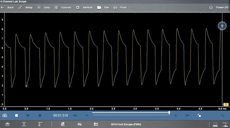
Figure 2
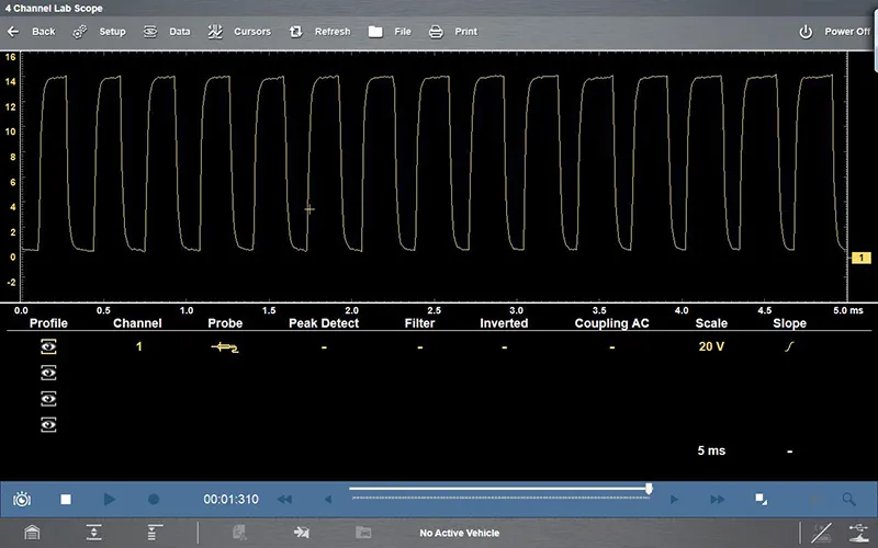
Figure 3
I now knew that I have a bad signal at the PCM and a good signal coming out of the unit, so my conclusion at this point was that there was an issue with the harness somewhere between the transmission and the PCM. I removed some components to gain access to the harness. After removing the battery and battery tray I noted that there was a lot of dried up corrosion in the battery tray as well as underneath it. Directly below the battery tray is where the harness was routed and I saw signs deterioration of the electrical tape and split loom. Could this be where my problem was? I then removed the taped and loom to expose the wires where I noticed the insulation on some of the wires didn't look quite right, and appeared swollen (Figure 4).
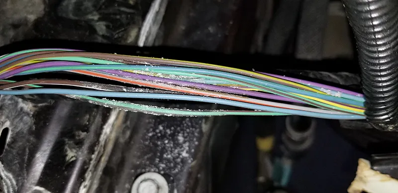
Figure 4
Back to the scope, I used a wire piercing lead and connected on the TCM side of the "swollen" wire (Figure 5) and had a good signal, then connected to the PCM side expecting to see the bad signal just like I had at the PCM, but did not; the scope reading looked normal. I really thought I had nailed down where the problem was, and visually I was not seeing anything else that looked out of place. I then realized what I had done; I had changed something didn't I? Yes, I did. These wires were all taped up tightly before I took the wire covering and the tape off, so I connected my lead back up to the PCM side of the loom and grabbed a hold of the wires where it looked damaged. I could get the scope pattern to change just depending on how hard I clenched my fist. (Figure 6) is a close up of one of the wires in question.
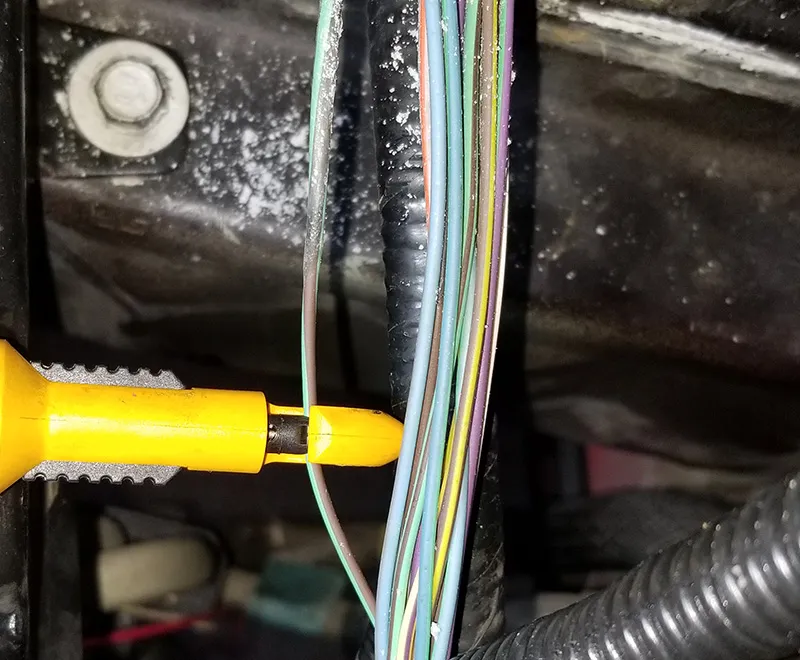
Figure 5
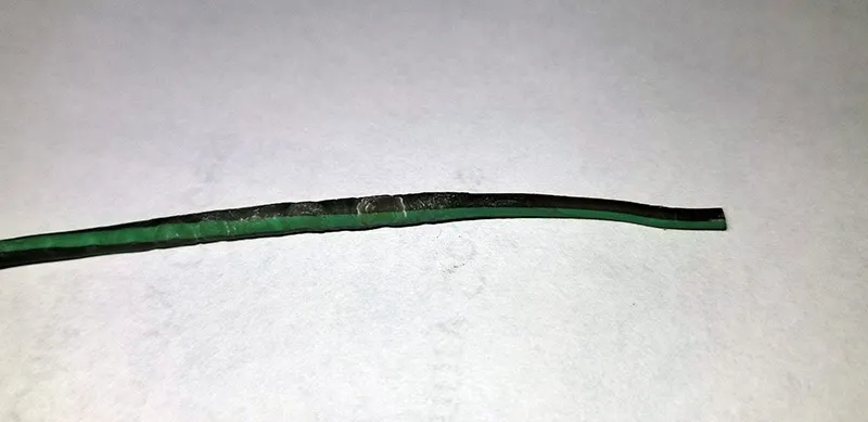
Figure 6
I carefully split the insulation to get a closer look at the inside of the wire. Upon getting the insulation split open I found a couple wires that had heavy corrosion. The worst one was circuit VET26 which was the output speed sensor signal to the PCM. I then cut out the bad section of the wires and installed new wires in their place. After the repairs were made I rechecked the signal at the PCM and it was now very clean. The vehicle now performed correctly on the test drive. While the wire inside the insulation was corroded, I do believe that it was more in the breakdown of the wire insulation not being able to shield the wire from induced voltage than the corrosion of the wire itself.
It's pretty common for the obvious issues (corroded battery and tray) to point you in the right direction when it comes to strange electrical issues. It's always a good idea to address these obvious issues first, and check the general area around it. Doing so can save a lot of unnecessary diagnosis time when dealing with electrical gremlins such as this.