
After a severe storm soaked the town, a 2006 Volvo S80 arrived at the shop with a troubling list of symptoms: failure to start, erratic drivability, a whining noise, and enough dashboard warnings to light up Times Square. The customer mentioned the car had sat in roughly seven inches of water, never a good omen for any modern vehicle. Like every car that rolls into our shop needing an evaluation, I grabbed my scan tool and documentation and headed out to begin the process.
Volvo, along with other German and Swedish manufacturers, tends to structure fault codes differently than the standard "P-Codes" (e.g., P0300 or P0420) that are common in domestic and Asian vehicles. These manufacturers use manufacturer-specific codes that require deeper familiarity and access to technical libraries. During the pre-scan, nearly every onboard control module reported a communication-related DTC; this pointed to a wide-reaching CAN network fault.
When I turned the key expecting a crank-no-start scenario, I was surprised to find no crank at all. I cleared all DTCs hoping to reestablish module communication, but even after ten cycles of the ignition, the car only reluctantly came to life. Still, I had zero access to ECM or TCM data streams, and the modules were silent.
Despite limited communication, the customer had driven the car to the shop, so I decided to take it for a controlled test drive to replicate the concern. That's when things got even stranger: inconsistent throttle response, erratic gear shifts, and a dash cluster blinking on and off. The issues weren't limited to one system, they were systemic. The scan confirmed multiple module-level faults:
- Engine and Transmission Control Modules (ECM & TCM):
- E000: Internal communication fault
- Anti-lock Brake System (ABS) Module:
- E000: Communication issue
- E003: Incorrect software version
- Right front wheel speed sensor fault
- Central Electronic Module (CEM):
- DF11/DF14/DF15: CAN High/Low signal too low or missing
- Communication loss with brake, audio, engine, and differential modules
The CEM stood out not only because of the quantity of DTCs, but also because it serves as the gatekeeper to the high-speed CAN network. Time to dig deeper.
Volvo's CEM setup is less than ideal; it houses the ECM and TCM on a slider-style tray with pin-based connections on the bottom and no stabilizing structure on the top. This allows both modules to rock slightly while driving, which can loosen pins over time. I pulled the mechanism and inspected the pins visually but found no obvious wear or corrosion.
At this stage, I needed a solid understanding of the architecture of the CAN network on this car. I referenced a technical diagram outlining the hierarchy of module communication. Unsurprisingly, the CEM was the first node in the high-speed network line.
When you're dealing with multiple communication faults, a lab scope becomes invaluable. I tapped into the CAN Hi (pin 6) and CAN Lo (pin 14) at the Data Link Connector (DLC). A healthy CAN signal typically involves differential voltages oscillating in the 2.5V-3.5V range for CAN Hi and 1.5V-2.5V for CAN Lo. My screen showed...nothing. Zero voltage. (Figure 1)
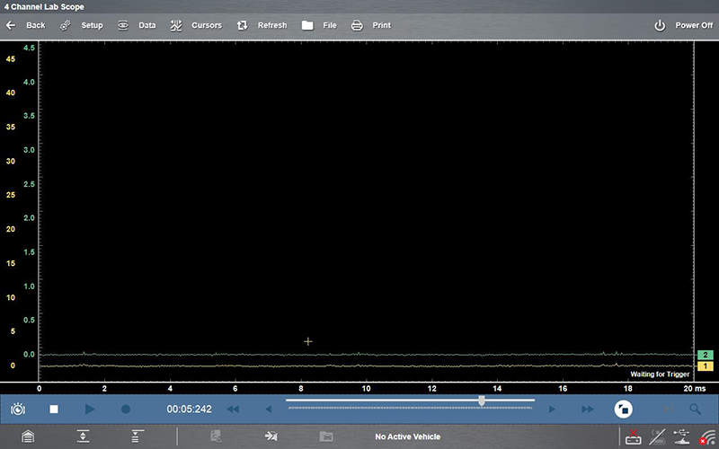
Figure 1
I began unplugging suspected modules one by one:
- ECM and TCM: No change.
- ABS module: Still dead voltage.
- Rear Differential Module: Waveform restored, communication resumed instantly.
That module appeared to be the culprit. Mounted directly onto the rear differential, it had likely sat submerged in water. Upon closer inspection, I found a pinhole rupture in the sealant, enough for water to breach and internally short the circuitry. One failed module was pulling down the entire network. (Figure 2)
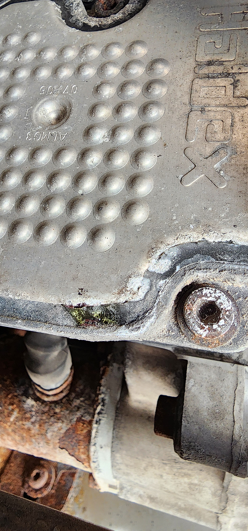
Figure 2
With the faulty differential module unplugged, the vehicle cranked promptly, the throttle responded normally, gear shifts stabilized, and communication was restored across every previously silent module. The transformation was dramatic and confirmed that the network itself was healthy, just hampered by a single corrupted node. (Figure 3)
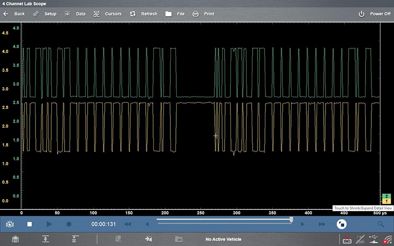
Figure 3
This job was a reminder that advanced diagnostics go far beyond code scanning. Understanding signal integrity and module topology made all the difference.
Best Practices for Diagnosing CAN Network Failures:
- Start With a Scope, Not Just a Scanner
- Flat-line or low-voltage signals are definitive indicators of a communication fault. Without scope validation, you'll miss silent errors or misattribute symptoms.
- Know Your Bus Topology
- Manufacturers structure their networks differently. Study the communication diagram to identify which modules are up/downstream in the CAN hierarchy.
- Unplug Modules Strategically
- Systematically remove modules to isolate the fault. In this case, the failed differential control module masked issues that would've otherwise pointed to the CEM.
-
Inspect Environmentally Vulnerable Modules
- Differential, fuel tank, and body control modules are exposed to moisture. Even tiny fractures in sealant can lead to catastrophic electrical behavior.
- Don't Assume Common Causes
- No crank doesn't always mean a starter or battery problem. If the network is down, even critical start commands might not propagate.
- Keep Your Technical Libraries Updated
- Having access to OE-level diagrams and fault code translations for European vehicles is essential. These aren't your typical "P-codes"; they require a deeper dive.