
1999 Chevrolet C30 7.4L 4L80E
The subject vehicle that was fitted with one of our remanufactured transmissions 6 months prior showed up at one of our repair locations recently, with the customer concern of an intermittent bumpy 1-2 shift, and a low power lugging sensation along with a CEL on. While performing our initial evaluation, we found a P1860 code stored in history, but not current. During the road test the truck was working well with no clear signs of what set the DTC, but after several minutes of driving it then started to act up. The TCC was applying right on top of the 1-2 shift, but according to the scan tool data, was not being commanded on by the ECU.
To diagnose the issue, a wiring diagram and a code description were printed and reviewed; this is a typical circuit for a GM transmission. The fuse feeds power to the transmission shift and TCC solenoids through pin 'E' at the case connector, and the power then runs through the solenoids and back to the VCM. The VCM is responsible for grounding the circuit to energize the solenoids. The TCC solenoid in this application is a PWM type and the computer duty cycles it on to provide a smooth engagement. A comprehensive battery and charging system test was performed to make sure that there was adequate voltage for proper circuit operations.
With this knowledge I decided to first check to see if there was B+ at pin '7' (brown wire at the C2 connector of the VCM) with KOEO. [FIG 1] If there wasn't any voltage drop at that location I knew the circuit was complete with no opens or shorts to ground, and if there was a voltage drop I would start backwards from the VCM to look for an open/short in the circuit. There was B+ at pin '7', so I hooked up my scope to test the circuit with the scanner using the bilateral controls and then drive the vehicle to see if the problem would occur.
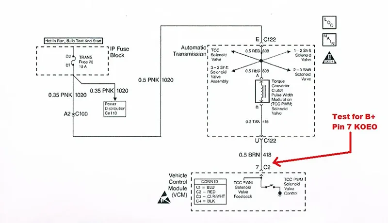
Figure 1
I back-probed pin '7' at the VCM to monitor the voltage with my scope lead, and then I put an amp clamp around the brown wire to monitor amperage [FIG 2]. Using the Tech2Win software to cycle the TCC solenoid, I could see the voltage drop to 0 and the current went to approximately 0.8 amps. The specification for the solenoid is 10-15 ohms. Using Ohm's Law I could quickly see that the amp reading was close without pulling out my calculator, at least close enough that it would not trigger a code. Now it was time to run the cables into the cab and go for a test drive.
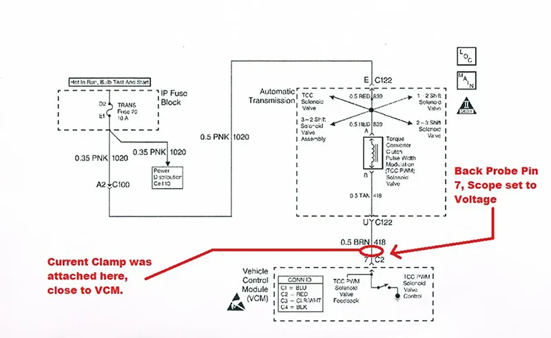
Figure 2
After driving a couple of miles the engine temperature was up and the TCC came on. The pattern was picture perfect. The VCM cycled the PWM solenoid and then completely grounded it to apply TCC fully. The amperage was what I was expecting to see [FIG 3].

Figure 3
It took quite a few more miles before the incident recurred. I took off from a stop, shifted to second and TCC was fully applied. I looked at the scope and saw that the voltage was very erratic but near zero, the amperage was at zero and the DTC also set. How could the voltage be at zero with the TCC is on, and there is NO Amperage going through the circuit? [FIG 4] Smarter men than I would know the answer to this right away. I just could not wrap my head around it at the time. Solenoid on, TCC applied, no current flow. I had to sleep on this one.
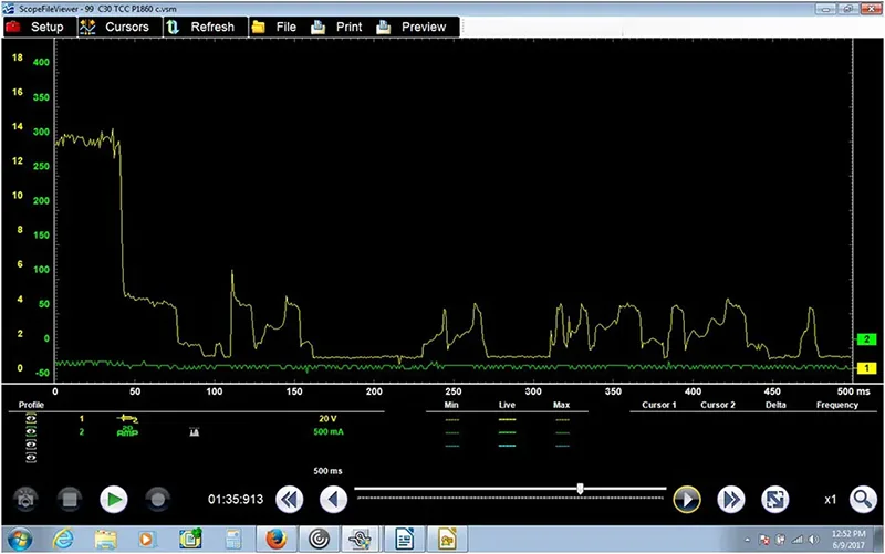
Figure 4
The next day Carman (shop Diagnostician) and I were discussing how there could be a completed circuit, the TCC solenoid on, TCC working and no amperage in the circuit. We were ready but not willing to replace the VCM. We then noticed a harness at the rear of the engine lying on the EGR tube. We lifted it up and used a mirror to see if it had burnt through, and it had [Fig 5].
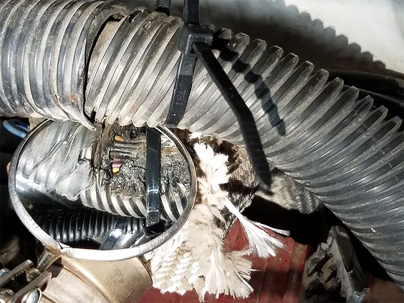
Figure 5
We determined this was the main harness to the transmission and our TCC control wire was in there. We strapped the harness up and away from the EGR tube and went for a drive [FIG 6].
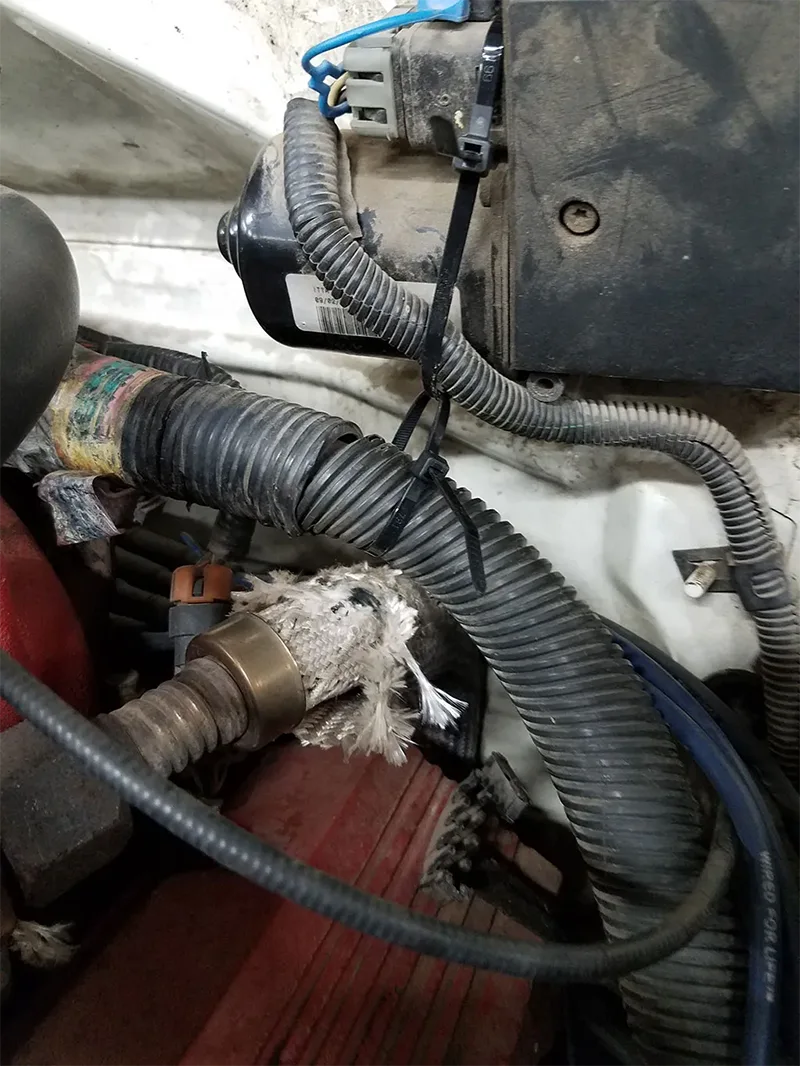
Figure 6
The transmission and the TCC worked flawlessly. Carman then dissected the harness and found our brown wire was burnt and shorting to the EGR tube. [FIG 7]
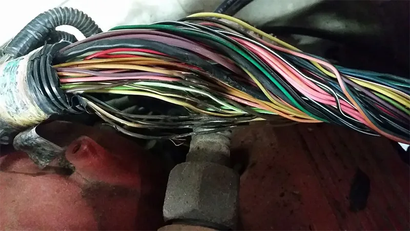
Figure 7
After a few minutes of thought, the mystery in my mind was solved. There were supposed to be a couple of harness retaining clips that held the harness up off of the EGR tube that were missing/broken that allowed the harness to come in contact with the EGR tube. There was also still enough wire insulation left that when it cooled off the short to ground was not present until the EGR tube got hot enough to melt through the insulation and bring the circuit to ground. So why did the circuit ground, solenoid function, TCC on and no current detected in the circuit? It was my current clamp placement! The circuit was completed at the EGR tube from the fuse instead of the VCM supplying ground. My amp clamp was outside of that circuit, as I had placed the amp clamp very close to the VCM connector C2. The VCM in turn would not ground the circuit because the code had set once the brown wire touched the EGR tube and no longer sensed voltage at the VCM. Had I used a fuse buddy loop and had the amp clamp at the fuse box, I would have seen the amperage when the wire shorted. At that point I could have certainly condemned the VCM for randomly grounding the circuit and I would have been very wrong. Sometimes it's good to be lucky.
Note: Someone, a.k.a. me, did not zero his amp clamp on some of the scope captures. That is why it looks like it is below 0 amps.