
The call started the way many of them do - with a frustrated customer. And in this case, the frustration was justified.
The vehicle had already been through two transmission replacements and a turbine speed sensor replacement. Despite those repairs, the original complaint remained. Under heavy acceleration - most noticeably from a stop, but occasionally during aggressive throttle application on the highway - the vehicle would surge, feel as if it went neutral, and then re-engage with a harsh bang. Just prior to the neutral sensation, engine RPM would flare noticeably.
Adding to the confusion, the condition was intermittent. Sometimes the vehicle would operate normally for weeks. Other times, the problem would occur every time the throttle was applied aggressively. Intermittent issues are challenging enough. Intermittent issues that persist after major component replacement demand a structured and disciplined diagnostic approach.
I began the process the same way I always do - by gathering as much detail as possible. The customer described the event as feeling like "a hard kick in the seat." In earlier occurrences, DTCs P0717 and P0718 had been stored. Both are turbine speed sensor (TSS) circuit codes indicating signal issues.
However, the most recent time the concern occurred, there were no active DTCs present. A repair facility had scanned the vehicle and found no stored codes. Interestingly, they did report seeing a fault recorded within the scan tool's PID fault data history. That detail was important. It suggested that even if the PCM did not set a full DTC, it may have briefly detected an irregularity.
Another key piece of information: after any repair or adaptive reset, the vehicle would operate normally for a short period - sometimes a day, sometimes a week - before the issue returned. That pattern suggested something marginal or intermittent rather than a consistent mechanical failure.
The next step was duplicating the complaint. On the first road test, the vehicle behaved exactly as described. The condition required aggressive throttle input from a stop. Light acceleration would not produce the concern.
The scan tool was configured to monitor turbine speed, output speed, commanded gear, actual gear, calculated gear ratio, and shift solenoid states. Rather than attempting to analyze the data live while driving, I recorded the event for review back at the shop.
Once the recording was reviewed and converted to graph form, an interesting pattern emerged. There was no obvious turbine speed dropout visible in the scan data. However, there was a drastic change in calculated gear ratio even though the commanded gear and actual gear did not change.
That raised a fundamental question: what would cause a calculated ratio change without an actual gear change?
The PCM determines gear ratio by comparing turbine speed (input speed) to output shaft speed (OSS). If the calculated ratio suddenly deviates while the transmission remains mechanically in the same gear, one of the inputs used to calculate that ratio must be inaccurate - even if that inaccuracy is brief.
Although no turbine speed dropout was obvious on the scan recording, the history of TSS-related DTCs could not be ignored. Scan tools sample data at limited rates. A very brief signal interruption may not appear clearly in scan data but can still be long enough to disrupt PCM calculations.
At this point, it was time to move beyond the scan tool and turn to a lab scope.
I began by monitoring the shift solenoids to rule out erratic solenoid control. During repeated hard acceleration events, the solenoid patterns remained stable even when the surge and harsh re-engagement occurred. That effectively ruled out a hydraulic control issue.
Attention shifted to the turbine speed sensor circuit.
At the PCM connector, I back-probed the TSS signal, power, and ground circuits (Fig. 4). The TSS shares its power and ground with the output speed sensor and transmission range sensor. Since there were no complaints associated with those components, a shared power or ground issue was unlikely - but verification is mandatory.
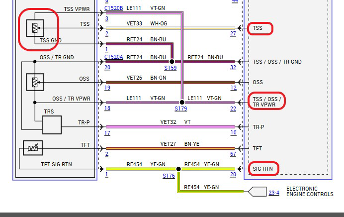
Figure 4 Back-probing PCM connector to monitor TSS power, ground, and signal circuits.
Under hard acceleration, the scope revealed the turbine speed signal dropped out momentarily while power and ground remained stable (Fig. 1). That brief dropout was enough to cause the PCM to miscalculate gear ratio and respond aggressively when the signal returned.
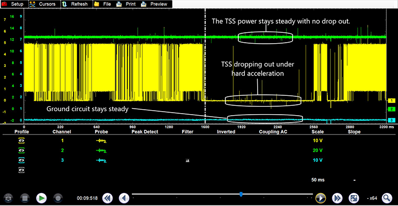
Figure 1 Lab scope capture showing turbine speed sensor signal dropout during hard acceleration while power and ground remain stable.
The root cause had been narrowed to the turbine speed signal circuit.
The turbine speed sensor is accessible once the air cleaner assembly is removed (Fig. 2). Inspection of the previously replaced pigtail showed no obvious installation concerns. A wiggle test at the connector with the engine running produced no signal interruption.
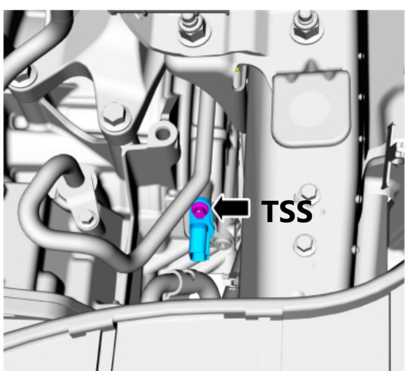
Figure 2 Turbine speed sensor location with air cleaner assembly removed for access.
To isolate the fault location, I added a probe directly at the TSS connector to compare the waveform at the sensor with the waveform at the PCM. During repeated throttle events, the signal at the sensor remained clean and stable. However, the signal at the PCM continued to show intermittent dropout.
That confirmed the fault was not the sensor itself, but somewhere between the sensor and the PCM.
Tracing the harness revealed it routed along the intake plenum, around the front of the engine, then back through the firewall toward the PCM (Fig. 5). Visual inspection showed no obvious chafing or exposed wiring.
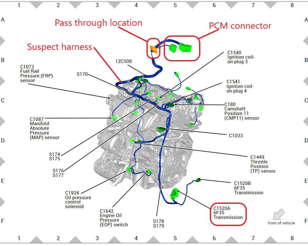
Figure 5 Harness routing across intake plenum and toward firewall pass-through where chafing occurred.
However, near the firewall pass-through, the harness rested against an A/C line. There were light rub marks on the loom, but nothing visibly severe.
A systematic wiggle test was performed, starting near the transmission and working back toward the PCM. The signal remained stable until reaching the section near the firewall where the harness bent around the A/C line. Manipulating that section consistently produced a turbine speed signal dropout on the scope (Fig. 3).
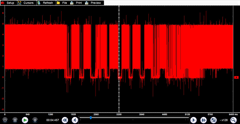
Figure 3 Scope capture during harness manipulation near firewall showing induced TSS signal interruption.
Even without visible conductor damage, the internal wiring had been compromised enough to intermittently open under load or movement.
THE REPAIRRather than disassembling and unwrapping the entire harness to locate the exact break point, a new dedicated TSS signal wire was run independently of the compromised section. The new wire was properly routed, protected, and secured away from potential chafing points.
Repeated hard acceleration testing showed a stable waveform with no dropouts. Calculated gear ratio remained consistent with commanded gear. No RPM flare occurred, and no harsh re-engagement was felt.
A final road test with the vehicle owner confirmed the repair. Multiple aggressive throttle applications produced normal operation. After months of frustration and multiple major repairs, the issue was resolved with a single corrected signal wire.
LESSONS FROM THE CASEThis case reinforces several important diagnostic principles:
- Scan data does not always reveal brief signal interruptions. Lab scopes provide higher resolution and should be used when intermittent electrical faults are suspected.
- A calculated gear ratio change without an actual gear change indicates corrupted input data.
- Shared power and ground circuits must be verified but not assumed faulty without evidence.
- Replacement components do not eliminate wiring faults.
- Harness movement under load can expose marginal wiring conditions not visible during static inspection.
The transmission was never the problem. The PCM was reacting to corrupted data. Once accurate information was restored, normal operation followed.
Electrical faults continue to challenge technicians, particularly when they mimic mechanical failure. Understanding how modules calculate their decisions - and verifying the integrity of the data they rely on - remains one of the most valuable skills in modern drivetrain diagnostics.