At Certified Transmission, our new-unit rollout process has evolved into a highly engineered workflow designed to ensure complete technical validation long before a product reaches a customer. The Ford 8F35 has been on our development radar for some time, and like all units we bring into our reman program, it requires a comprehensive sequence of engineering checks, hardware analysis, calibration verification, and controlled functional testing. Operating as a remanufacturer places us in a unique position relative to many independent shops; we cannot release a transmission until every subsystem-from hydraulics to shift logic-has been characterized and proven repeatable. Quality remains our absolute priority, and establishing a repeatable build process for a new unit demands coordination across a wide technical front: parts sourcing, specification documentation, builder training, solenoid and valve body testing, dyno strategy, and installation validation.
Engineering Intake and Core EvaluationOur first step in any new-unit program is establishing the exact application range and identifying which core families we must acquire. For the 8F35, we sourced both standard mileage cores and extremely low-mileage examples (typically under 1,000 miles). These low-wear units allow us to benchmark "factory fresh" specifications: clutch clearances, selective fit locations, end play, and valve body vacuum integrity. Measurements from these baseline units become reference points for our builder spec sheets and test limits. Depending on the application, we may also disassemble and reman the valve body of a virgin unit to confirm expected solenoid flow rates, spool bore conditions, and pressure-control repeatability.
Next, we obtain a low-mileage vehicle to serve as our calibration and dynamics test mule. For the 8F35, we acquired a 2024 Ford Edge equipped with the 2.0L EcoBoost. This step is essential for gathering actual operational data-thermal behavior, clutch-to-clutch timing, adaptive response, commanded vs. achieved pressure, shift execution order, and TCC strategies. These parameters later inform both our dyno program and our post-build quality verification procedures.
Calibration Verification and Initial ObservationsBefore any engineering data collection, we ensure the vehicle is running the latest ECM/TCM calibrations. Using the Ford VCM2 with FDRS, we verified the module firmware and applied available updates. Interestingly, even after calibration, no additional relearn procedures were required; the unit performed consistently before and after. A short 25-mile drive cycle was performed to verify thermal stability, shift quality, and adaptation behavior.
At the retail level, all Certified Transmission stores use Snap-On Zeus scan tools. While no single tool captures every parameter perfectly, Zeus paired with ShopStream Connect provides excellent resolution for recording and reviewing scan data. This becomes especially valuable when comparing commanded values to measured pressures, adaptive corrections, and solenoid control duty cycles.
One notable early discovery was that our so-called "8-speed" transmission was not always operating as an 8-speed. In the 2024 Edge, 2nd gear is never commanded under any operating condition-not launch, light throttle, moderate acceleration, nor manual selection. After researching Ford service literature, the OEM confirms the behavior:
"This transmission may also be described as a 7-speed. For 7-speed applications, 2nd gear is not utilized."
What appears to be a traditional 8-speed architecture is functionally operating as a 7-speed in certain calibrations. This skip-shift strategy significantly changes shift timing, clutch loading distribution, and adaptation profiles. It also affects how the dyno sequence must be programmed, since the system must never be forced into a ratio the TCM is not designed to utilize.
High-Resolution Hydraulic and Solenoid Analysis
To characterize hydraulic behavior, we used one of our more advanced engineering tools - the Yokogawa DL850 Scopecorder. With sample intervals set at 10 us, the scope provides extremely high-fidelity recordings of solenoid command, pressure sensor output, and external pressure transducer voltages.
Observed Stall Pressure Characteristics (Figures 1 & 2)
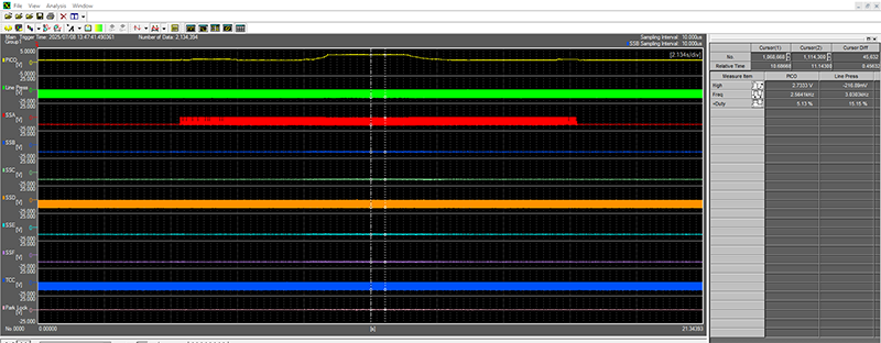
Figure 1
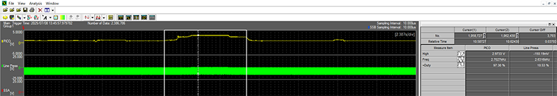
Figure 2
(All readings from the benchmark low-mileage 8F35 Edge)
- Reverse Stall: 297 psi
- LPC solenoid at 10% duty (essentially full shutoff)
- Drive Stall: 275 psi
- LPC solenoid at 16% duty
- Idle in P/N: 75 psi
- LPC solenoid at 48% duty
- Initial Drive engagement: line pressure spikes to ~110 psi
- Idle in Drive: 75 psi
- LPC at 42% duty
- Initial Reverse engagement: line pressure spikes to ~100 psi
- Idle in Reverse: 75 psi
- LPC at 45% duty
These readings confirm that the 8F35 uses an aggressively modulated line pressure strategy, with the LPC solenoid providing nearly the entire range of commanded adjustments. Because the solenoid is continuously modulating, slight variations in duty cycle are expected and can be influenced by pump volumetric efficiency, internal leakage, or solenoid wear.
Sensor Correlation AnalysisOne of the more interesting engineering findings was the tight agreement between commanded line pressure, internal pressure sensors, and external measurement:
- In Reverse stall, commanded pressure was 307.1 psi, while Sensor B reported 308.2 psi. (Figure 3)
- Using a Pico WPS500X transducer, the corresponding stall event produced 2.9733 V, converting to 297 psi. (Figure 1)
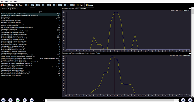
Figure 3
Figure 1
Although the handheld scanner, on-board sensors, and external transducer were not capturing data simultaneously, the readings consistently fell within ~10 psi of one another across idle and stall conditions. That level of correlation suggests the 8F35's internal pressure sensors may be sufficiently accurate to serve as a functional diagnostic reference-assuming no sensor rationality faults. For the aftermarket, this can reduce the need for mechanical pressure gauges in certain diagnostic scenarios.
Gear-to-Gear Line Pressure BehaviorA full sweep from 1st through 8th gear (recorded at 3000 rpm) demonstrates predictable and repeatable adaptive modulation. Each commanded shift produces a distinct line-pressure elevation corresponding to clutch-to-clutch transfer. These pressure peaks reveal the adaptation magnitude the TCM requires to maintain shift quality. As the unit ages or internal leakage develops, these pressure profiles will shift-often an early indicator of clutch wear or bore degradation. (Figure 4)
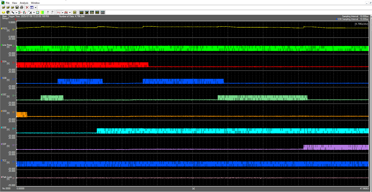
Figure 4
Our 8F35 new-unit rollout is progressing through the engineering and validation stages. The skip-shift behavior, close correlation of internal sensors to actual pressure, and well-controlled solenoid modulation all contribute to what appears to be a highly adaptive and tightly controlled transmission platform. As we finalize our builder specifications, dyno scripts, and valve body testing parameters, the engineering data gathered from this low-mileage Edge provides a strong foundation for a reliable remanufactured product.