
We had replaced the transmission in a 2004 Chevrolet Trailblazer and when the owner returned for a 15-day recheck, the customer mentioned that he had felt a hard shift at times. During my checks I found P0748 (Pressure Control Solenoid A Electrical) stored in the PCM history along with P0455 (Evaporative Emission Control System Gross Leak Detected). The truck had the engine code stored prior to our original repairs, and the owner was advised that those needed attention and he wasn't concerned that the check engine lamp was on. I focused my attention to the P0748 as it was pertinent to the transmission.
A short road-test confirmed that the shifts were indeed hard, and the scan data showed no desired amperage to the pressure control solenoid, causing a default to full line pressure. After recording the freezeframe records I cleared the codes to enable the output function of the scan tool, then tested the PC solenoid and the actual amperage stayed consistent with the command, indicating that this was not a hard fault. We now had an intermittent problem to chase.
Wanting to cover the basics, I tested the battery and charging systems, inspected cable and ground connections, and ran some ground voltage drop tests but no problems were found. Out on a longer road-test (bringing the truck up to full operating temperature) the code did not reset, and the transmission shifted well. I then shut the truck off and let it hot soak for 15 minutes, then started on another drive. A hard 1-2 shift started right away. A recheck of codes revealed that the P0748 had reset. I retested the pressure control with the scan tool outputs which showed the actual still always matched the command amperage, so I commanded the output mid-way and did a wiggle test on the related harnesses and connectors that I could access. There were no variations in the actual amp readings on the scanner.
Next, I disconnected the connectors at the transmission and the PCM to inspect the terminals. No issues were found, so I reconnected the transmission and then connected my ohmmeter to the PC control circuits at the PCM connector. The resistance was a little on the high side (6.3Ω) of specifications (3-7Ω), but still within spec. A wiggle test of harness checked good, also. I decided to do a dynamic test of the circuit by connecting my ammeter inline with the circuits connected to the battery and had 1.7A slowly dropping. I again wiggled harnesses and saw no glitches, then rechecked the resistance and found it had climbed to 8.3Ω. Not a solid fault, but I decided to replace the PC solenoid and inspect the internal harness while the pan was off.
No problem was seen with the internal harness and the PC solenoid, but I decided to replace them both to avoid removing the pan again. I then road-tested getting up to full operating temperature, did a hot soak for 10-15 min., retested, and repeated three more times with no hard shifts or P0748 resetting. Thinking I had it fixed, I returned the truck to the owner.
Just over a week later the owner was back with the truck stating the hard shifts had started again. A scan test of the codes showed that the P0748 did in fact return. After bringing the truck up to temperature and letting it hot soak a few minutes, before the first shift on the road-test the code reset with a hard shift. A retest of the transmission circuits from the PCM connector didn't reveal any resistance or current concerns. With a voltmeter connected to the low side of the PC circuit in MIN MAX mode, I found that the circuit would spike to system voltage just as the code reset and the circuit drivers shut off. I decided to disconnect the harness from the transmission to pull it out in the open where I could see all of it so I could look it over closely just to rule out the possibility of a pinched wire that might be hidden somewhere. After feeling confident the harness had no visible issues, I attached the lab scope to the PC control circuits and captured a failure event. (Figure 1).
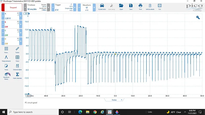
Figure 1
Although it was clear that the PCM driver was shutting down, it was unclear to me why. I decided to substitute another PCM only to have the same condition return after driving and restarting several times. At this point I needed to put it to the side and sleep on it, and although I never really get these problems out of my head, it helps me to look at it from a new perspective. After studying what else may be happening in the engine controls, I did notice that the camshaft actuator controls used the same High/Low setup as the PCS did, so I decided to take a look. (Afterthoughts, I should have bought a lottery ticket that day).
With the lab scope connected across the cam actuator solenoid circuits it was confirmed that the actuator turned on under the same driving conditions that the PC control fault happened, and that the wave pattern was unusually low, indicating current limiting in the PCM driver. (Figure 2) (the actuator circuit is the blue trace)
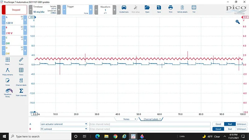
Figure 2
The circuits tested good back to the PCM with no shorts to power or ground. The solenoid resistance tested good, but when I tested the current through the solenoid by grounding the low side terminal and applying battery power through my ammeter, the display jumped to OL indicating high current flow of a shorted winding. The cam actuator solenoid was replaced and retested with a scope pattern more what I would expect to find. (Figure 3)
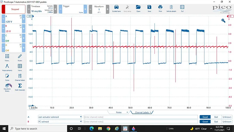
Figure 3
The scope was reconnected to the transmission control circuits and driven several times with a crisp circuit pattern and no faults before delivering the vehicle back to the owner. (Figure 4)
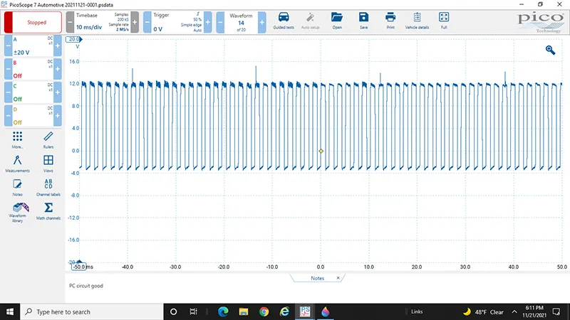
Figure 4
With the vehicle repaired I was still confused as to why it hadn't set any cam control codes when it clearly had a fault in that circuit. Why was the system setting a fault in the PCS circuit instead? Study of the circuits showed that they are both are a pulse-width modulated control to the solenoids. With both the high reference and the low reference being controlled by the PCM, my theory is that when the cam solenoid was hot and the "turn on" current was high the winding shorted momentarily (as I duplicated when applying full current with my ammeter) spiking the reference low circuits internal of the module interrupting the current flow to the PC solenoid and triggering the fault.
As for it not setting a code for the cam timing system, I attribute that to the logarithms in the fault detection system not being perfect. Getting away from relying on just a static test of the circuits (i.e., resistance) but doing a dynamic test (current) sometimes is the only way to recreate the fault with coil windings in solenoids and relays. At the end of the day, the extra time put in found the fault and corrected the customer's issue.