
Vehicle: 2009 Mercedes Benz E350 AWD.
Engine: 3.5 V6, Transmission: 722.6.
Customer Concern: 30-40 mph is the top speed, drive modes won't switch, neutrals out in reverse, stuck in low gear at times, can't shift manually, only works in drive.
Stored DTC 2767, Component Y3/6n3 (speed sensor) is faulty.
Prior to any diagnostics, I performed the initial code scan and road test. There was an unrelated engine code stored, but the DTC I was interested in was the 2767 stored for the transmission. 2767 is a manufacturer-specific code relating to the Y3/6n3 speed sensor. There are 2 speed sensors on the conductor plate that the TCM uses. Y3/6n2 is active whenever the vehicle is moving, be it forward, or reverse. Y3/6n3 is used in second, third and fourth gears.
The data PID for the Y3/6n3 speed sensor was showing a flat line and the reading was 8000 rpm with the code present (FIG 1).
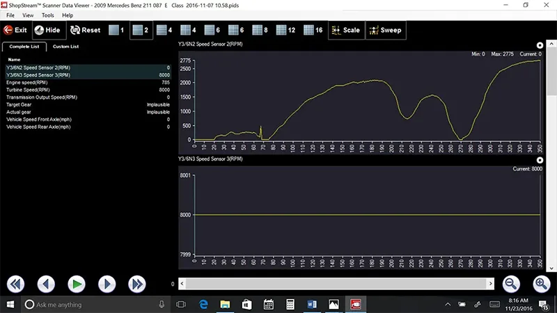
Figure 1
I made all my notes, cleared the code and drove the vehicle. The transmission worked well, shifted through all the gears and showed speed signals on both speed sensors on the scan data (FIG 2).
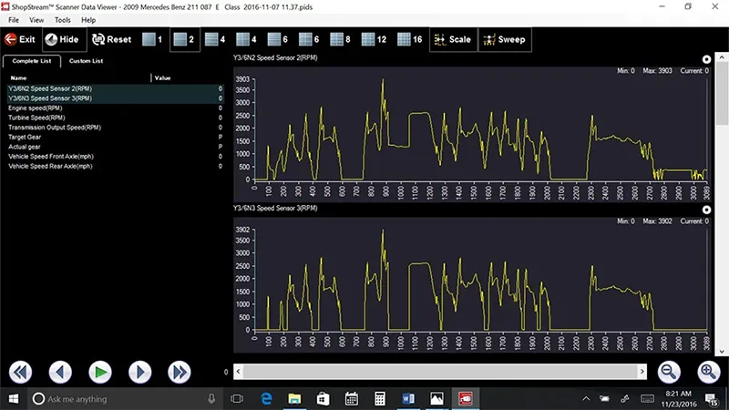
Figure 2
After the initial road test and data gathering, I made the request to get more time authorized to perform more in-depth diagnostic testing. The call was made and the customer agreed to let us go ahead with testing.
After a short time looking for information, wire diagrams and pin out charts, I found most of the information on this vehicle was for a 722.9 transmission. This vehicle has the 722.6 transmission in it. I had to comb through several sources to find the information I needed. After printing and reviewing the information I was ready to dig into this further (FIG 3).
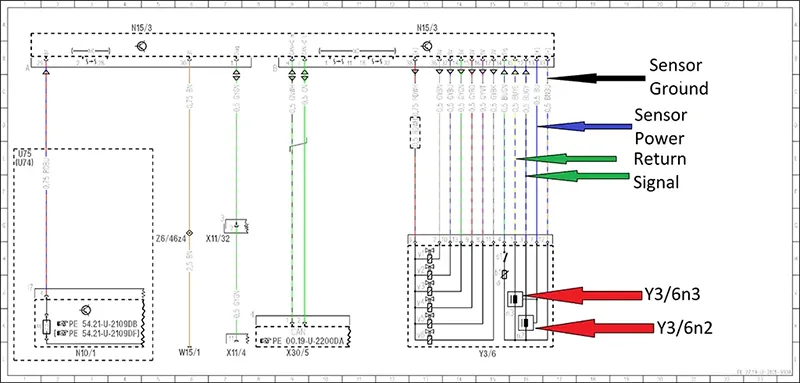
Figure 3
The TCM is located on the passenger side under the carpet towards the front. The nice thing is that Mercedes makes it somewhat easy to access. Pull the carpet back, locate the 3 nuts that hold the mounting plate, pull it out and the TCM is now out in the open. Locating the circuits I needed to monitor, I set up the scope (FIG 4).
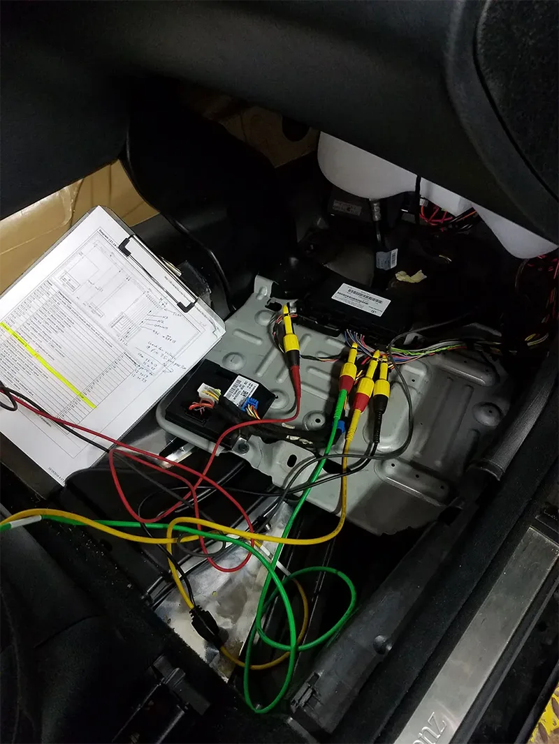
Figure 4
I'm going to monitor both Y3/6n2 and Y3/6n3. These are 3 wire sensors, power, ground and signal. They make a 0.0 to 6.0 Volt square wave pattern. I attached a probe to each signal wire and grounded it to the circuits' ground wire at the TCM (FIG 3). I also connected a DVOM to the ground wire and the battery ground to watch for voltage drop on the ground circuit. I had a scan tool connected to watch the PID data on the Y3/6n2 and Y3/6n3 speed sensors. I was watching to see what was happening when the code sets.
I started out on the road test with everything connected. My speed sensor patterns were a good square-wave pattern going from 0.0 volts to 6.0 volts (FIG 5), and the voltage drop on the ground was constant at 0.06 volts.
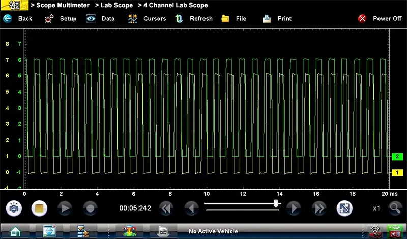
Figure 5
I get on the highway, shift transmission to 4th gear. In 5th gear the Y3/6n3 does not record any speed signal. I drove for about 4 miles when the Y3/6n3 signal started to drop (FIG 6).
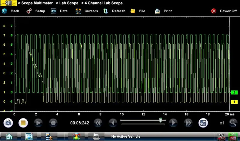
Figure 6
It fluctuated between working and dropping to less than 0.5 volts (FIG 7).
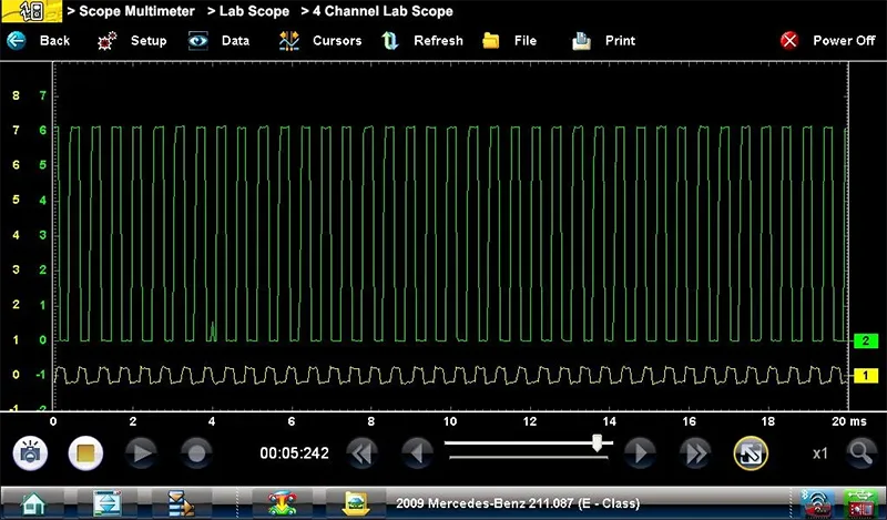
Figure 7
What was interesting was the transmission was still in 4th gear and the PID reading was normal (FIG 8).
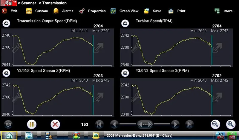
Figure 8
Nothing had changed on the scan tool and no DTC was set. I got off the highway and performed several stop-and-go maneuvers. The transmission was working correctly, the PIDS were normal, and the voltage was still below 0.5 volts on the scope. What in the world is going on? The sensor is malfunctioning, yet the PID is normal and the transmission still functions and shifts correctly.
I developed a theory that, even though the speed sensor voltage is very low, the computer sees some sort of action and must use the other speed sensors to maintain transmission shifting. The speed sensor must completely fail, 0.0 volts (flat line), for the DTC to set. I let the vehicle cool down and repeated the process again and got the same outcome. I still have no code and not sure why. I could not get the speed sensor to completely fail to confirm my theory. I removed the Y3/6n3 wire from the TCM connector (FIG 9).
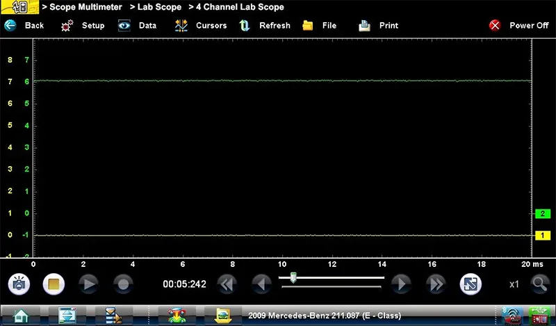
Figure 9
The Y3/6n3 sensor does not monitor in 1st gear but starts monitoring in 2nd. There was no KOEO or KOER code because I removed the sensor return wire and not the power or ground wire. I would not see an effect until the transmission shifted to 2nd gear. TCM would still see voltage through the sensor on startup (FIG 3). If I had removed the power or ground wire I'm sure I would have set a KOEO code. As I started down the road as soon as it shifted to 2nd gear the check engine lamp came on, the vehicle jerked and the DTC set the speed sensor PID was flat line at 8000 rpm (FIG 10).
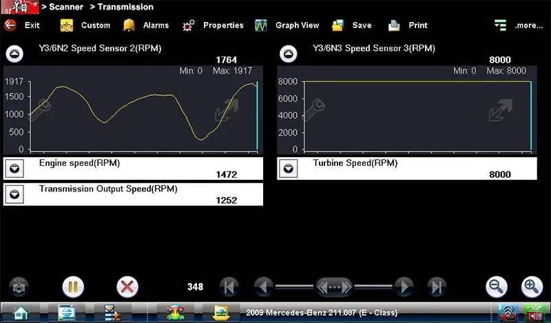
Figure 10
I stopped, cleared the code and repeated the process. I got the same results. If the code was present, the vehicle remained in failsafe and the PID read 8000 rpm. I then reconnected the signal wire, cleared the code and drove the vehicle. The sensor had the low voltage but the vehicle shifted and the PID was normal.
I was confident I'd proven my theory and recommended speed sensors (conductor plate) be replaced. The customer agreed to the repairs and we installed the new parts.
I left the equipment hooked up for the final road test. I initially drove the vehicle 10 miles on the highway in 4th gear. The sensor patterns were good, 0.0 volts to 6.0-volt square wave pattern (FIG 11 & 12).
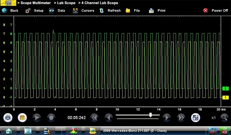
Figure 11
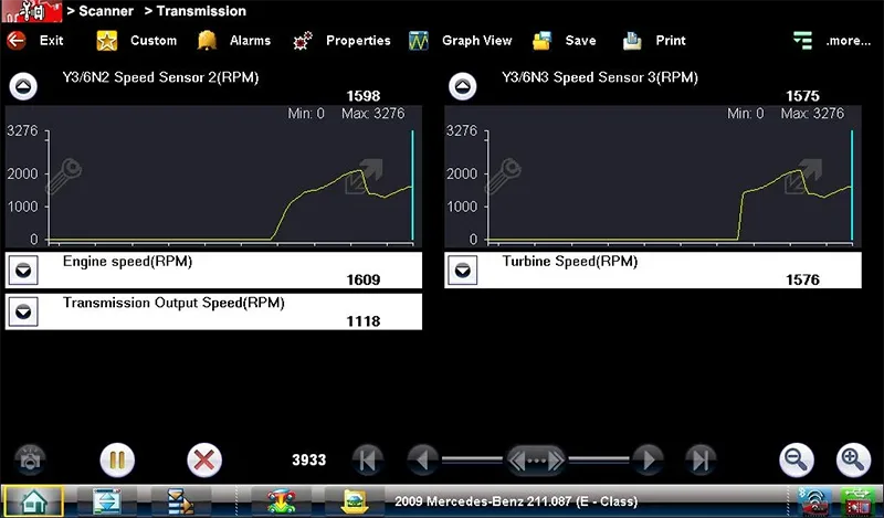
Figure 12
Driving back to the in stop-and-go traffic the pattern never dropped. I was happy with the results. I removed my scope set up and put the passenger side area back together. I drove the vehicle one more time with only a scan tool connected. Again another 10 miles and everything was normal (FIG 13).
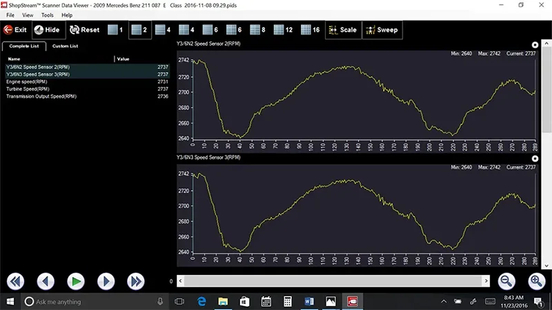
Figure 13
There were a couple difficult and confusing things about this diagnosis. First, I had a very difficult time finding the technical information for the 722.6 (5 speed) transmission for this vehicle. Nearly all the information I found was for the 722.9 (7 speed) transmission. This delayed the diagnostic process. Second, even though the sensor had virtually no signal, the transmission still operated correctly. The sensor had to completely fail for the transmission to go into fail safe. I could not find that documented anywhere I searched. It may be out there somewhere. There are too many times at the shop level we don't have spare time, but luckily, I had enough time to perform the diagnostics, develop a theory and prove that theory.