
It seems that we have run into several different vehicles in the recent past that have had stacked shifts, and shifted into overdrive by 20 mph. While the symptoms were common, the diagnosis and repairs were very different. The following are a few briefs on what we found.
The first was in a 1999 GMC dump truck that another shop had been working on for some time, and could not determine what the problem was. They had replaced the PCM with a new one, and had checked all the sensors and the speedometer and the computer were displaying the correct speed.
I checked the signals from the speed buffer and all showed a good signal on the lab scope, but then as I followed wiring diagrams I discovered that there were two signal wires from the speed buffer to the computer. A check of the connector view and a trace of the wiring revealed an open circuit in the harness of one of the reference signals, labeled "A/T ISS Sensor". Since this signal is a requirement for the PCM to properly time the shifts, the open circuit was the cause of the early shifts. A quick repair of the wiring solved this issue.
The next truck was a 1994 C1500 Chevy pickup that came in with a burned up transmission. After the installation of a remanufactured unit, we discovered that this vehicle had stacked shifts, and again this truck had fourth gear by 20 mph. Due to the inoperative original unit, we did not have an opportunity to drive the truck until we installed a new transmission. It is quite possible that the original unit failed due to the issues were we experiencing after the install.
The first place I went was to the speed buffer. After testing the signals and checking that the wiring was good, and unlike the previous case, I noted that this vehicle only had a single wire to the computer. Testing showed the correct reading on the speedo and the scan tool. As I followed the connector pin by pin, I discovered that it had a wire that was supposed to go to the transfer case module, (terminal F8 Dark Blue wire) but this was a two wheel drive not a four wheel drive and did not have a transfer case module to communicate with. I was not sure what the signal wire was shorted to, so I cut the wire at the computer and lo and behold, it had normal shifts. For some reason it was getting information from somewhere, possibly a short or ground to another circuit, but the computer thought that the non-existent transfer case was in four low and was shifting accordingly, even though the speedometer read the correct speed.
The next one I ran into was a 1995 S10 Blazer four wheel drive. It came from another shop that had been working on it for several days, trying to figure out the stacked shifts and fourth gear by 20 mph. I had an idea that the problem was the signal from the Transfer Case Module, but I could not find any data or information on what the signal should be to the PCM. A simple disconnect of the Transfer Case Module and I had normal shifts. The replacement of the Transfer Case Module solved the problem on this one.
Our final example was an early 90's Toyota Corolla. It came into the shop with no movement and burnt fluid, so the unit was pulled to go through the remanufacturing process. After install again I had another vehicle with stacked shifts, and fourth gear by 20 mph.
Time to get out the lab scope and check the output speed sensor. The test revealed that there was a great deal of static from the sensor. We tried to find another speed sensor but none was available from any source, so I tried a remedy that I have used for years on the Dodge trucks that experienced torque converter cycling on and off after lockup. This procedure filters out the noise on the signal wire from the throttle position sensor to the computer so that the computer can read the signal without the static.
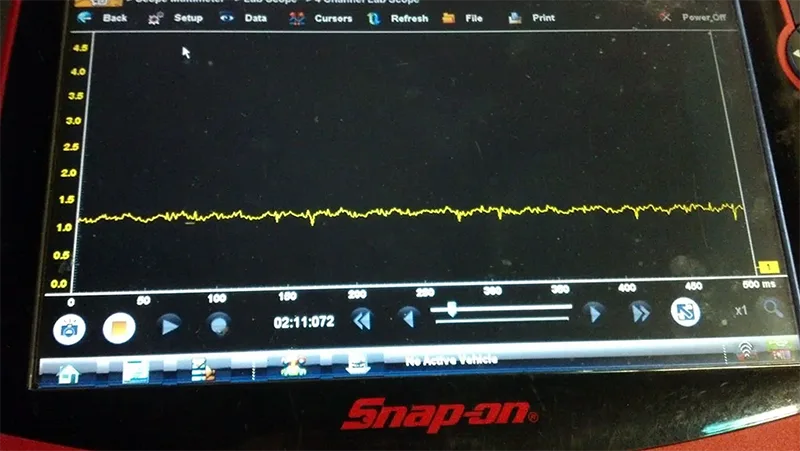
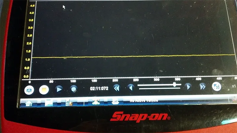
ATRA has made available all the information for the rectifier to remove any unwanted noise, with the part numbers from Radio Shack. Pick up a resistor part #271-1328 (3300 ohm) and a capacitor #272-1436 (10uF), and on the signal wire you wish to clean up, put the 3300 ohm resistor inline, and the 10uF capacitor between the resistor and the computer. The longer lead on the capacitor attaches to the signal wire and the shorter lead attaches to ground. If you look at a before and after signal at the computer, you will see a signal with static (FIG 1) and after the signal rectifier a flat signal with no static (FIG 2).
After installing this rectifier on the Toyota, the shifts were normal and the customer was satisfied.
Note that although the symptoms in all of these cases were the same, the repairs were slightly different but with one commonality to them: the issue centered on some form of speed sensor signal issue. Unless the diagnostics lead you to a component problem, a little trial and error may be required to get to the root cause of the problem. The books won't always lead you there. One thing to remember is that if all of the shifts are there, albeit stacked and erratic, the cause is likely electrical. With a little patience and time, the cause will reveal itself.