
Late-model vehicles continue to challenge technicians with increasingly complex electronic integration, especially in transmission control systems. What once required mechanical linkage, and simple hydraulic logic now depends heavily on sensors, modules, and network communication. A recent case involving a low-mileage 2020 Buick Enclave equipped with the 9T65 illustrates how critical accurate data interpretation has become in modern diagnostics.
This vehicle arrived from a nationwide used car dealership with just 33,600 miles on the odometer. At first glance, this low mileage might lead some to assume a minimal likelihood of internal transmission failure. However, as many experienced technicians know, mileage alone is no longer a reliable indicator of component integrity, especially when electronics are involved.
Initial Complaint and ObservationsThe primary complaint was straightforward: the vehicle was stuck in Park and unable to be shifted into gear. Upon initial inspection, one of the first noticeable symptoms was that all the gear selector indicator lights on the center console were flashing simultaneously. (Figure 1)
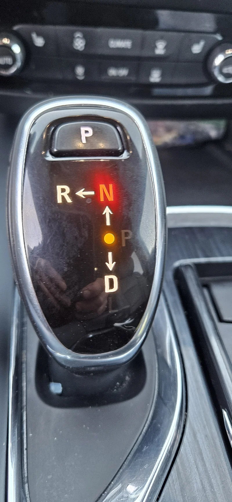
At the same time, the instrument cluster displayed a warning message: "Service Transmission Now - Unable to Shift."
This vehicle utilizes an Electronic Transmission Range Select (ETRS) system, meaning there is no physical shift cable connecting the gear selector to the transmission. Instead, driver input is interpreted electronically and relayed to the transmission control system. While this design offers packaging and efficiency advantages, it also introduces additional diagnostic complexity when faults occur.
Code Retrieval and System BehaviorA full system scan revealed a current diagnostic trouble code: P187E (Transmission Park Valve Stuck Off). Notably, the code would not clear, indicating an active fault rather than a stored or intermittent condition.
At this point, it was important to verify whether the transmission was physically stuck in Park or if the issue was electronic in nature. With the rear driveshaft removed and the front wheels lifted off the ground, the wheel would not turn. This confirmed that the vehicle was indeed held stationary, but not necessarily by the transmission itself.
Further investigation revealed that the electronic parking brake system was actively engaged. While it could be temporarily released using the manual park release switch, the brakes would immediately reapply once the switch was released. This behavior was directly tied to the active P187E code, as the system was preventing vehicle movement due to an unresolved Park status fault, an intentional safety feature.
Data Analysis: The Turning PointAt this stage, scan data became the most valuable diagnostic tool. Monitoring the Transmission Park Valve Position Sensors, two critical inputs were evaluated:
- Park Valve Position Sensor 1: 0.80 volts - Status: In Park
- Park Valve Position Sensor 2: 1.98 volts - Status: Out of Park
Additionally, the system reported the overall parking status as "Unknown". (Figure 2)
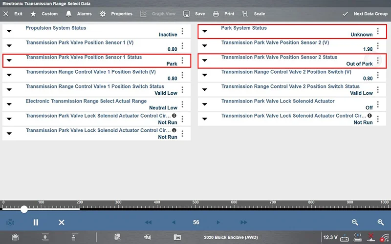
This conflicting data was a major clue. The control module received two different signals regarding the actual position of the park valve. In a system designed with redundancy and safety in mind, disagreement between sensors results in a fail-safe condition - in this case, preventing the vehicle from moving by keeping the parking brake applied.
At this point, it became clear that the issue was not simply mechanical. Instead, it was a discrepancy between sensor inputs, leading to a logic-based lockout.
Diagnostic Direction and Repair DecisionBased on the available data, there was strong evidence pointing toward an internal issue within the valve body assembly - specifically involving the park valve position sensing components. No other irregularities were observed in the scan data, reinforcing the likelihood of a localized internal fault.
The dealership was presented with two repair options:
- Replace the valve body, with a limited warranty, or
- Install our remanufactured transmission with a full warranty
Given the circumstances and warranty considerations, the decision was made to proceed with a remanufactured transmission replacement.
Following installation, programming, and code clearing, the vehicle operated as expected with no further issues. From a service standpoint, the repair was complete.
But the diagnostic story didn't end there.
Root Cause AnalysisRather than stopping at the successful repair, a deeper investigation was performed on the original transmission to identify the exact root cause of the failure.
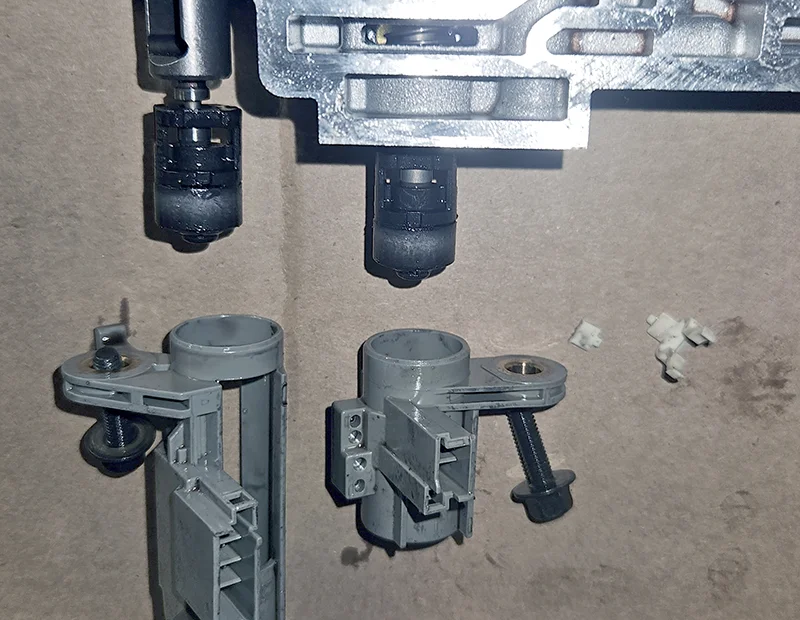
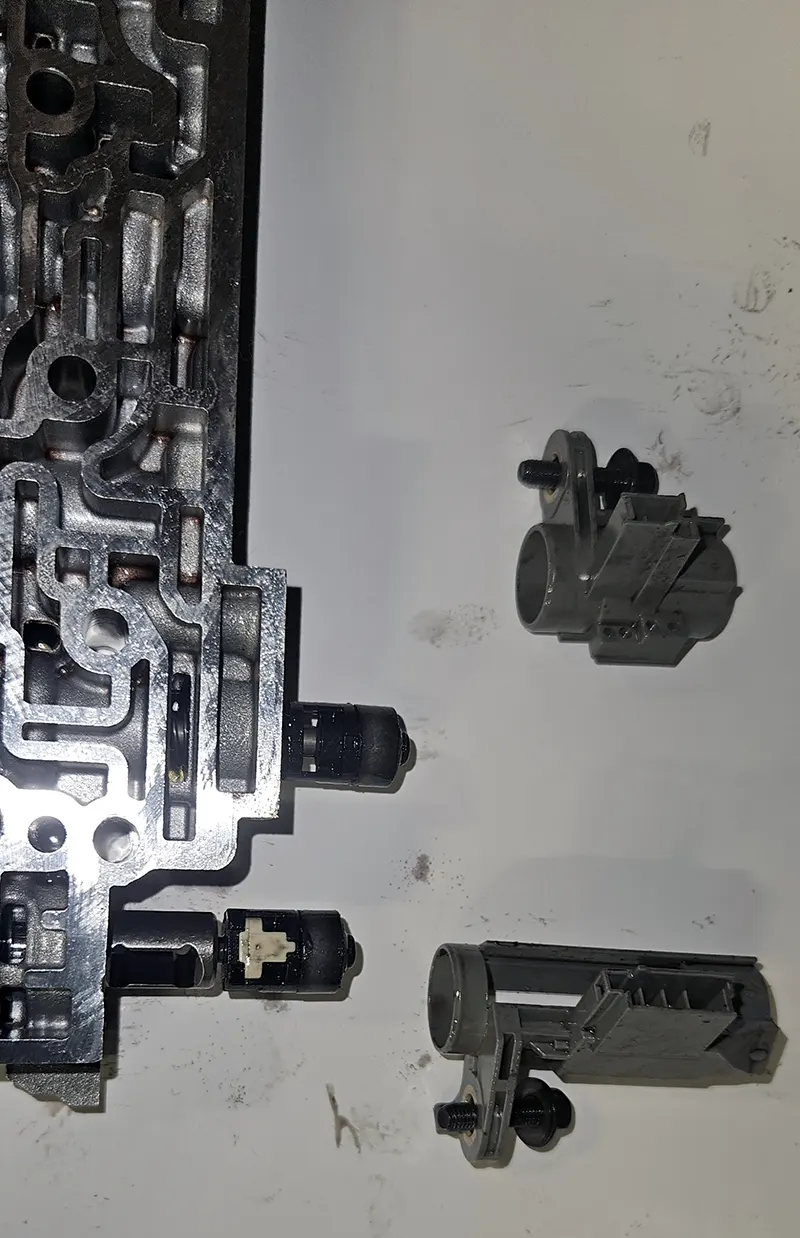
After removing the valve body cover, there were no immediate visual signs of damage or sticking components. However, given the earlier scan data indicating disagreement between park position sensors, attention was focused on the mode valve and associated position sensors.
The mode valve-to-position sensor assembly was removed for closer inspection. Initially, no obvious issues stood out. However, upon removing the Mode Valve Position Sensor 1, the failure became clear. The plastic retaining clip that secures the sensor magnet to the position valve was broken. (Figure 3 & 4)
The park valve position sensors in this system are supplied with approximately 9 volts from the control module, and they return a signal voltage typically ranging between 0.80 and 2.0 volts, depending on valve position.
With the retaining clip broken, the magnet was no longer physically linked to the valve's actual movement. As a result, the sensor remained fixed in an "out of park" position, regardless of the true mechanical state of the valve.
This created a scenario where:
- One sensor accurately reported "Park"
- The other sensor falsely reported "Out of Park"
The control module, unable to reconcile the disagreement, defaulted to a fail-safe strategy, setting code P187E and preventing vehicle movement by engaging the parking brake.
Key Takeaways for TechniciansThis case highlights several important lessons for today's transmission diagnosticians:
- Data Interpretation is Critical
The scan data in this case directly identified the issue. Without careful analysis of sensor voltages and status, the root cause could easily have been misdiagnosed. -
Verify Before You Replace
While the final repair involved replacing the transmission, the diagnostic process itself proved that the failure was isolated to a small internal component. Understanding these failures can influence future repair decisions and reduce unnecessary replacements. - Electronic Systems Can Mimic Mechanical Failures
Although the vehicle appeared to be mechanically stuck in Park, the root cause was entirely electronic. Modern systems often blur the line between mechanical and electronic faults. - Redundancy Can Create Unique Failure Modes
Dual-sensor systems improve safety but also introduce scenarios where disagreement between inputs causes system lockout - even when part of the system is functioning correctly. - DTCs Are Only the Starting Point
The P187E code identified the system involved but did not pinpoint the exact failure. It was the supporting data that led to an accurate diagnosis.
As transmission systems continue to evolve, successful diagnostics increasingly depend on a technician's ability to interpret data, understand system logic, and verify component operation beyond surface-level symptoms.
In this case, what initially appeared to be a major transmission failure was ultimately traced back to a small broken plastic clip. The scan tool provided the roadmap, but it took a methodical approach and a willingness to dig deeper to uncover the true cause.
This is a clear example of how getting the job done right starts with understanding what the vehicle is actually telling you.